Do you have a question about the Cisco CBS Series and is the answer not in the manual?
Details the various LEDs on the switch's front panel, including system and stack status indicators.
Explains how to access and manage the switch via its IP network using the web-based interface.
Details the steps for configuring the switch via its console port, requiring specific terminal emulation settings.
Describes the two display modes available in the web GUI: Basic and Advanced configuration options.
The Cisco CBS Series Switch is a robust networking device designed to provide powerful network performance and reliability for business networks. It offers a comprehensive suite of network features, going beyond the capabilities of unmanaged or consumer-grade switches. These switches are expandable, featuring Gigabit Ethernet ports with options for Gigabit or 10-Gigabit uplinks. They support multiple management options, robust security capabilities, and Layer-3 static routing features, all at a more cost-effective price point than fully managed switches.
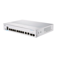
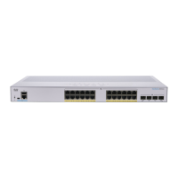
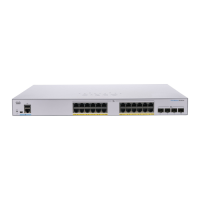
The primary function of the Cisco CBS Series Switch is to facilitate network connectivity and management within a business environment. It acts as a central hub for connecting various network devices such as computers, printers, IP cameras, VoIP phones, and wireless access points. The switch supports Power over Ethernet (PoE) on specific models, allowing it to supply power to attached powered devices (PDs) directly through the Ethernet cable, simplifying deployments and reducing cable clutter.
The switch can operate in a standalone configuration or as part of a stack. Stacking allows multiple switches to be managed as a single logical unit, increasing network capacity and simplifying administration. Any 10G port on the switch can be used for stacking, and the ports can be configured to function either as regular Ethernet ports or as stacking ports. The device supports both Native Stacking, where all units in the stack are of the same type, and Hybrid Stacking, which allows for mixed types of CBS350 devices within a single stack. When stacking, it's crucial that stack ports have the same speed capability.
The switch offers various management options, including a web-based interface for graphical configuration and a command-line interface (CLI) accessible via a console port for advanced users. The web-based interface provides an intuitive way to configure the switch, while the console port offers more granular control and is particularly useful for initial setup or troubleshooting.
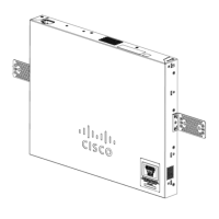
The Cisco CBS Series Switch can be installed in several ways:
The switch features RJ-45 Ethernet cables for connecting network devices. For 10G ports, a category 6a or higher cable is required, while for all other ports, a category 5e or higher cable is sufficient. Some models include SFP+ (small form-factor pluggable plus) ports, which are connection points for modules that allow the switch to link to other switches, often referred to as mini 10GigaBit Interface Converter ports. Some SFP interfaces are shared with RJ-45 ports, forming "combo ports," where activating the SFP disables the adjacent RJ-45 port.
PoE-enabled models can supply DC power to devices like VoIP phones, IP cameras, and wireless access points. It's important to note that PoE switches are Power Sourcing Equipment (PSE). To prevent false detection issues where a PoE switch might mistakenly detect another PSE as a powered device, it is recommended to disable PoE on ports connecting to other PSEs and to power up PSE devices before connecting them to a PoE switch.
The switch offers a web-based interface for configuration. To access it, users need to connect their computer to a network port on the switch and enter the switch's IP address into a web browser. The default IP address is 192.168.1.254, with a subnet of /24. The default username and password are "cisco" (case sensitive). Upon first login, users are prompted to change these default credentials for security. The web-based interface supports various browsers, including Microsoft Edge, Firefox (version 82 or higher), Chrome (version 86 or higher), and Safari over MAC (version 14.0 and higher).
The web-based interface provides two display modes:
A console port (RJ-45 and/or mini-USB) is also available for CLI access, requiring a serial cable and terminal emulation program. This method is typically used by advanced users for initial setup, troubleshooting, or when network access is unavailable.
The stacking feature allows for increased network scalability and simplified management. When switches are stacked, they function as a single unit. The system LED on each unit indicates its Stack ID and whether it is the active unit. It's crucial to maintain consistent stack speeds across all switches and ports within a stack.
The front panel includes various LEDs to indicate the switch's status:
The Reset button on the front panel serves two key maintenance functions:
The switch includes a USB port that allows users to save and restore configuration files, firmware images, and SYSLOG files using a connected USB device. The USB port supports the FAT32 file system. This feature is crucial for backing up configurations and quickly deploying consistent settings across multiple switches or after a reset.
Upon initial login, users are required to change the default username and password to enhance network security. The system enforces password complexity rules to ensure strong credentials.
The console access provides additional interfaces for debug access, which are intended for Cisco Support Team personnel. These interfaces are password-protected and allow for U-BOOT access during the boot sequence, Linux Kernel access during the boot sequence, and run-time debug modes. The run-time debug mode, accessible over telnet and SSH terminals in addition to the console, allows the support team to view device settings and apply protocol and Layer 1 debug commands.
While not explicitly detailed as a maintenance feature, the ability to save and restore firmware images via the USB port implies that firmware updates are a supported maintenance activity, allowing the switch to benefit from new features, performance improvements, and security patches.
Overall, the Cisco CBS Series Switch is designed for ease of use, robust performance, and flexible deployment, with features that cater to the evolving needs of small to medium-sized business networks.
| Category | Switch |
|---|---|
| Port Speed | 10/100/1000 Mbps |
| Operating Temperature | 0°C to 45°C (32°F to 113°F) |
| Dimensions | Varies by model |
| Weight | Varies by model |
| Series | CBS Series |
| Management | Web-based, CLI |
| Layer | Layer 2 |
| PoE | Available on some models (PoE and PoE+) |
| Uplink | SFP |
| Mounting | Desktop or rack-mountable |
| Switching Capacity | Varies by model |
| Forwarding Rate | Varies by model |
| VLAN Support | Yes |
| QoS | Yes |
| Security Features | ACLs, 802.1X authentication, Port Security |
| Management Interface | Web GUI |
| MAC Address Table Size | Varies by model |
| Jumbo Frame Support | Yes |
| Energy Efficiency | Energy Efficient Ethernet (EEE) |
| Ports | Varies by model (8, 16, 24) |