EasyManua.ls Logo

Cisco CBS 250 Series - User Manual

Cisco CBS 250 Series
12 pages
Print Icon
To Next Page IconTo Next Page
Loading...
Get To Know Your Switch
This chapter contains the following sections:
Introduction, on page 1
Rack Mounting Switch, on page 2
Wall Mounting a Switch, on page 3
Power over Ethernet Considerations, on page 5
Front Panel, on page 7
Configuring Switches, on page 9
Navigation, on page 11
Introduction
Thank you for purchasing the Cisco CBS 250 Series Switch. The Cisco CBS 250 Series Switches are the next
generation of affordable smart switches that combine powerful network performance and reliability with a
complete suite of network features that you need for a solid business network. These expandable Gigabit
Ethernet switches, with Gigabit or 10-Gigabit uplinks, provide multiple management options, rich security
capabilities, and Layer-3 static routing features far beyond those of an unmanaged or consumer-grade switch,
at a lower cost than fully managed switches. With an easy-to-use web user interface, Smart Network
Application, and Power over Ethernet Plus capability, you can deploy and configure a complete business
network in minutes.
Before You Begin
Before you begin installing your device, ensure that the following items are available:
RJ-45 Ethernet cables for connecting network devices. A category 6a and higher cable is required for
10G ports; a category 5e and higher cable is required for all other ports.
Tools for installing the hardware.
The rack-mount kit packed with the switch contains four rubber feet for desktop placement, and
two brackets and twelve screws for rackmounting.
If the supplied screws are lost, use replacement screws in the following size:
Diameter of the screw head: 6.9 mm
Length of face of screw head to base of screw: 5.9 mm
Get To Know Your Switch
1
Question and Answer IconNeed help?

Do you have a question about the Cisco CBS 250 Series and is the answer not in the manual?

Summary

Introduction

Before You Begin

Ensures necessary items are available before installing the network switch.

Rack Mounting Switch

Rack Mounting Procedure

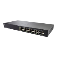
Details on mounting switches in a standard 19-inch rack unit, including steps and stability cautions.

Wall Mounting a Switch

Wall Mounting 24-Port Switch

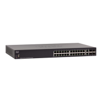
Steps for wall-mounting a 24-port switch using brackets, including safety cautions.

Wall Mounting 8-Port Switch

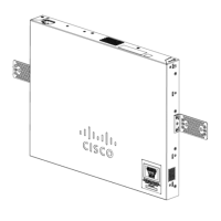
Instructions for wall-mounting an 8-port switch using mounting screws and a template.

Power over Ethernet Considerations

PoE Switch Compatibility and Usage

Details switch models supporting PoE and considerations for connecting powered devices.

PoE Safety and Detection Issues

Discusses potential PoE detection issues and safety precautions for PSE devices.

Front Panel

Front Panel Components

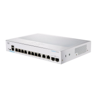
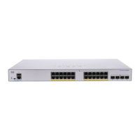
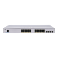
Identifies ports, LEDs, and buttons on the switch's front panel for management and connectivity.

Front Panel LED Indicators

Explains global and per-port LED indicators for system status, stacking, and network activity.

Configuring Switches

Web-based Configuration

Steps to access and configure the switch using its web-based interface, including default settings.

Console Port Configuration

Detailed steps for configuring the switch via its console port using a serial connection and terminal utility.

Navigation

UI Navigation Menu

Describes how to navigate the switch's web UI, including accessing features and subcategories.

Basic vs. Advanced Display Modes

Explains the differences between Basic and Advanced display modes in the web GUI and their impact on configuration options.

Overview

The Cisco CBS 250 Series Switch is a next-generation smart switch designed to provide powerful network performance and reliability for business networks. It offers a comprehensive suite of network features, combining advanced capabilities with an affordable price point, making it a suitable alternative to unmanaged or consumer-grade switches.

Function Description

The Cisco CBS 250 Series Switches are primarily designed for network connectivity and management. They feature expandable Gigabit Ethernet ports, with options for Gigabit or 10-Gigabit uplinks, to support high-speed data transfer across the network. These switches are equipped with Layer-3 static routing capabilities, allowing for more efficient data forwarding between different network segments.

For enhanced security, the switches offer rich security features to protect network resources and data. They also provide multiple management options, including an easy-to-use web user interface and a command-line interface (CLI) for advanced users. The integration of Power over Ethernet Plus (PoE+) capability on certain models allows the switches to power connected devices such as VoIP phones, IP cameras, and wireless access points directly through the Ethernet cable, simplifying deployment and reducing the need for separate power outlets.

The switches are designed to be deployed and configured quickly, with the Smart Network Application facilitating a complete business network setup in minutes. They support various network protocols and features to ensure robust and scalable network operations.

Usage Features

The Cisco CBS 250 Series Switch offers flexible deployment options, including rack mounting and wall mounting.

Rack Mounting:

Switches can be mounted in any standard 19-inch (approximately 48 cm) wide rack, occupying 1 rack unit (RU) of space (1.75 inches or 44.45 mm high). For stability, it is recommended to load the rack from bottom to top, placing the heaviest devices at the bottom to prevent tipping. The rack-mount kit includes two brackets and twelve screws for secure attachment. To install, one bracket is placed on the side of the switch, aligning the four holes with the screw holes, and secured with four screws. This process is repeated for the other side. Once both brackets are attached, the switch is ready for installation into a standard 19-inch rack.

Wall Mounting:

The switches can also be wall-mounted using wall studs or a firmly attached plywood mounting backboard. When wall-mounting, it is crucial to follow safety regulations and avoid mounting the switch with its front panel facing up to prevent airflow restriction and ensure easier access to cables. The recommended orientation is with the front panel facing down or to the side. For a 24-port switch, a 19-inch bracket is attached to one side, and then the other bracket to the opposite side. After securing the brackets, the switch is mounted with the front panel facing down, ensuring it is securely attached to wall studs or a plywood-mounting backboard. For an 8-port switch, a template is used to align the mounting screw holes. The template is positioned so that the side marked "CABLE SIDE ENTRY" faces the floor. The template is then secured to wall studs or a plywood backboard. The adhesive strip on the bottom of the screw template is peeled off, and the template is attached to the wall. Two screws (3.7 mm or #27 drill bit for a 12.7 mm hole) are inserted into the slots on the screw template and tightened to secure the template. Once the template is removed, the switch is placed onto the mounting screws and slid down until it locks in place.

Power over Ethernet (PoE) Considerations:

Certain models of the CBS 250 Series Switches support PoE, indicated by a "P" in their model number (e.g., CBSxxx-xxP-xx). These PoE switches act as Power Sourcing Equipment (PSE), supplying DC power to attached Powered Devices (PDs) like VoIP phones, IP cameras, and wireless access points. The switches can detect and supply power to pre-standard legacy PoE PDs. However, caution is advised as a PoE switch acting as a PSE might mistakenly detect and power another PSE (including other PoE switches) as a legacy PD. This can lead to improper operation of the PoE switch and its attached PDs. To prevent false detection, PoE should be disabled on ports connecting to other PSEs. It is also recommended to power up a PSE device with AC power before connecting it to a PoE switch. If a device is falsely detected as a PD, it should be disconnected from the PoE port, power-recycled with AC power, and then reconnected. The manual provides a table listing SKU names, descriptions, PoE PD Chipset Types, and PoE PSE Support (AF/AT) for various PoE models.

Front Panel:

The front panel of the switch features various ports, LEDs, and a Reset button.

  • Console Port: Includes RJ-45 and mini-USB connectors for serial cable connection to a computer, enabling configuration via a terminal emulation program. (Note: Only certain models support this feature.)
  • USB Port: Connects the switch to a USB device for saving and restoring configuration files, firmware images, and SYSLOG files.
  • RJ-45 Ethernet Ports: Connect network devices like computers, printers, and access points to the switch.
  • SFP+ Port (if present): Small form-factor pluggable plus (SFP+) ports are connection points for modules that link to other switches. These are also known as mini 10Gigabit Interface Converter ports. SFP+ ports are compatible with Cisco SFP 1G optical modules (MGBSX1, MGBLX1, MGBLH1, MGBT1) and other brands, as well as Cisco SFP+ Copper Cable modules (SFP-H10GB-CU1M, SFP-H10GB-CU3M, SFP-H10GB-CU5M). The LEDs for corresponding RJ-45 ports flash green to indicate SFP interface traffic. Some SFP interfaces are shared with an RJ-45 port (combo port); when the SFP is active, the adjacent RJ-45 port is disabled.
  • Reset Button: Used to reset or reboot the switch. A press of less than 10 seconds reboots the switch.

LED Indicators:

The switches feature global and per-port LEDs to indicate device status.

  • System LED (Green): Steady when powered on, flashes during booting, self-tests, or IP address acquisition. An Amber flash indicates hardware/firmware failure or a configuration file error.
  • Stack ID LED (Green): Steady when the switch is stacked, indicating its Stack ID.
  • Active Unit ID LED: Indicates the stack active unit.
  • System LED (Stacking): Flashes every 20 seconds according to the unit ID (1 flash for Unit 1, 2 for Unit 2, etc.), with an LED off time of approximately 0.5 seconds per flash and an "Interim" LED on time of 0.5 seconds between flashes. If a member unit is removed, its system LED continues to flash according to its last known definition.
  • LINK/ACT LED (Green): Located on the left of each port. Steady when a link is detected, flashes when traffic passes.
  • SFP+ LED (Green): Located on the right of a 10G port. Steady when a connection is made through the shared port, flashes when traffic passes.
  • XG LED (Green): Located on the right of a 10G port. Steady when another device is connected, powered on, and a 10 Gbps link is established. Off indicates speed under 10 Gbps or no cable.
  • Gigabit LED (Green): Located on the right of the OOB and 1G port. Steady when another device is connected, powered on, and a 1000 Mbps link is established. Off indicates speed under 1000 Mbps or no cable.
  • PoE LED (Amber): Located on the right of the port. Steady when power is supplied to an attached device.

Configuration:

Switches can be configured via a web-based interface or a command-line interface (CLI) through the console port.

  • Web-based Interface: The default IP address is 192.168.1.254 with a /24 subnet. The default username and password are "cisco." When using the default IP, the System LED flashes continuously; it becomes steady green when a DHCP-assigned or static IP is configured. To access, connect a computer to any network port, set the computer's IP configuration (e.g., 192.168.1.2 to 192.168.1.253 if using the default switch IP, or ensure DHCP is running). Open a web browser, enter the switch IP address (e.g., http://192.168.1.254), and log in with the default credentials. Upon first login, users are prompted to change the username and password, adhering to password complexity rules. Configuration changes must be saved by clicking the Save icon to avoid loss.
  • Console Port (CLI): Connect a computer to the switch console port using a Cisco console cable or mini-USB connector. Start a console port utility (e.g., HyperTerminal) and configure it with 115200 bits per second, 8 data bits, no parity, 1 stop bit, and no flow control. Log in with the default username and password ("cisco"). Similar to the web interface, first-time login requires changing credentials.

The web-based interface features a navigation menu at the top right of each UI page, listing main features. Users can access UI pages through cascading menus by clicking feature tabs and selecting subcategories. The product supports Basic and Advanced Display Modes.

  • Basic Mode: Provides a subset of common configuration options.
  • Advanced Mode: Offers the full set of configuration options. Switching between modes reloads the page. If a page exists in both modes, the user stays on that page; otherwise, the browser loads the first page of the folder or the Getting Started page. If advanced configurations exist but the page is in basic mode, a page-level message will be displayed. Any unsaved configurations are deleted when switching modes.

Maintenance Features

The Cisco CBS 250 Series Switches incorporate features that support ongoing maintenance and troubleshooting.

  • Console Access for Debugging: Beyond standard configuration, the console port provides additional interfaces for debug access, which are not available via the web interface. These interfaces are password-protected and intended for use by Cisco Support Team personnel to debug device behavior. Supported debug access interfaces include U-BOOT access during the boot sequence, Linux Kernel access during the boot sequence, and run-time debug modes. Run-time debug modes allow viewing device settings and applying protocol and Layer 1 debug commands and settings, accessible over Telnet, SSH, and console.
  • Configuration File Management: The USB port allows users to save and restore configuration files, facilitating backup and recovery processes. This is crucial for maintaining network settings and quickly restoring them in case of an issue or when deploying new devices with similar configurations.
  • Firmware Image Management: The USB port also supports saving and restoring firmware images, enabling easy firmware upgrades or rollbacks, which are essential for security updates, bug fixes, and new feature implementations.
  • SYSLOG File Management: SYSLOG files can be saved and restored via the USB device, providing a mechanism for collecting and analyzing system logs. These logs are vital for monitoring device health, identifying potential problems, and troubleshooting network issues.
  • Reset Button: The physical Reset button on the front panel allows for a quick reboot of the switch (press for less than 10 seconds). This can be a useful first step in troubleshooting minor issues or applying certain configuration changes that require a device restart.
  • LED Indicators for Diagnostics: The comprehensive set of global and per-port LEDs provides immediate visual feedback on the switch's operational status, link activity, speed, and PoE status. An Amber System LED, for instance, immediately signals a hardware or firmware failure or a configuration file error, guiding technicians to potential problem areas. Link/Act LEDs indicate connectivity and data flow, while PoE LEDs confirm power delivery to connected devices.
  • Password Complexity Rules: The system enforces password complexity rules during initial setup and subsequent changes, enhancing security and reducing the risk of unauthorized access.
  • Saving Configuration Changes: The web-based interface explicitly requires users to save configuration changes to prevent data loss. This prompt ensures that intentional modifications are preserved, while accidental changes can be discarded by not saving.
  • DHCP and Static IP Management: The ability to use either DHCP or static IP addresses, along with clear guidance on managing these settings, helps maintain network accessibility and prevents IP conflicts, which are common sources of network issues. The note about setting the IP address type to Static if DHCP is not used, and changing the static IP and subnet mask to match the network topology, is a critical maintenance consideration to avoid multiple switches using the same factory default IP address.

Cisco CBS 250 Series Specifications

General IconGeneral
ModelCBS250 Series
Operating Temperature0°C to 45°C (32°F to 113°F)
Port TypeGigabit Ethernet
PoE OptionsAvailable on select models (PoE, PoE+)
Switching CapacityUp to 104 Gbps
LayerLayer 2
ManagementWeb-based GUI, CLI
FeaturesVLAN, QoS, Port Mirroring
Security FeaturesACLs, 802.1X, Port Security
Form FactorRackmount, Desktop
Humidity10% to 90% non-condensing
Ports8, 24, 48
Jumbo Frame SupportUp to 9KB

Related product manuals