Consider the following when connecting a PoE switch. The PoE switches are PSE (Power Sourcing Equipment)
that are capable of supplying DC power to attaching powered devices (PD). These devices include VoIP
phones, IP cameras, and wireless access points. The PoE switches can detect and supply power to pre-standard
legacy PoE PD. Due to the PoE legacy support, it is possible that a PoE switch acting as a PSE may mistakenly
detect and supply power to an attaching PSE, including other PoE switches, as a legacy PD. Even though PoE
switches are PSE, and as such should be powered by AC, they could be powered up as a legacy PD by another
PSE due to false detection. When this happens, the PoE switch may not operate properly and may not be able
to properly supply power to its attaching PDs.
To prevent false detection, you should disable PoE on the ports on the PoE switches that are used to connect
to PSEs. You should also first power up a PSE device before connecting it to a PoE switch. When a device
is being falsely detected as a PD, you should disconnect the device from the PoE port and power recycle the
device with AC power before reconnecting its PoE ports.
Caution
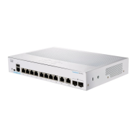
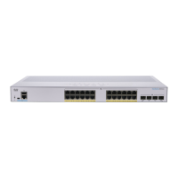
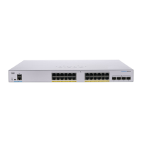
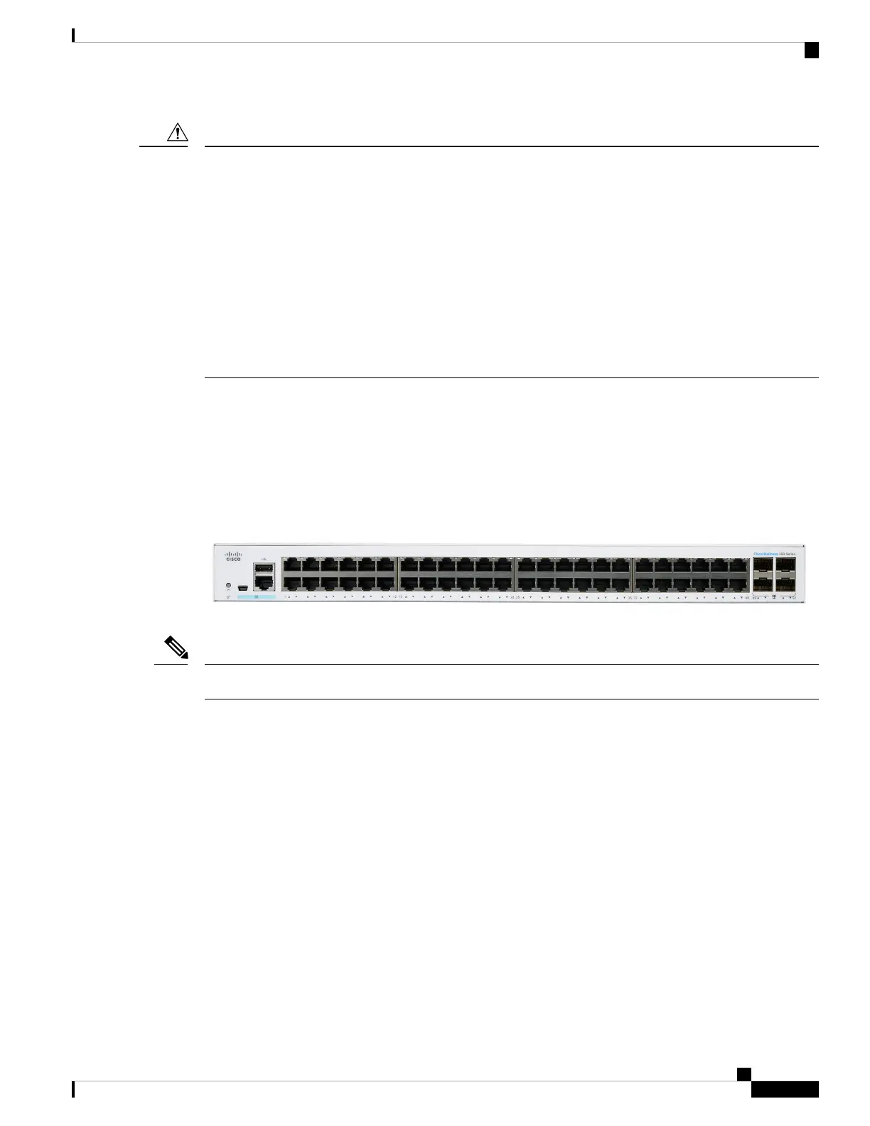
Front Panel
The ports, LEDs, and Reset button are located on the front panel of the switch, as well as the following
components:
Cisco Business 350 Series Model
Models may differ within the CBS 350 series and this is just a representation of a model within the series.
Note
• There are 2 device types with different console interface:
1. Console port with RJ-45 and mini-USB connector if both are connected the Mini USB has precedence
over the RJ-45
2. RJ-45 connector only type of console.
The console interface connects a serial cable to a computer serial port so that it can be configured using
a terminal emulation program or mini USB cable (depending on connector).
• USB Port—The USB port connects the switch to a USB device so that you can save and restore the
configuration files, firmware images, and SYSLOG files through the connected USB device. The USB
port supports the FAT32 file system.
• RJ-45 Ethernet Ports—The RJ-45 Ethernet ports connect network devices, such as computers, printers,
and access points, to the switch.
Get To Know Your Switch
9
Get To Know Your Switch
Front Panel