Installing the Chassis Ground Cable
This section describes how to install the chassis ground cable on the Cisco CRS Series Enhanced 16-slot Line
Card Chassis. For complete information on regulatory compliance and safety, see Regulatory Compliance
and Safety Information for the Cisco CRS Carrier Routing System .
Prerequisites
Before performing this task, perform the following procedures:
Required Tools and Equipment
You need the following tools and equipment to perform this task:
•
Ground lug
•
Ground cable
•
Crimping tool and lug specific die
•
3/8 in. drive socket wrench
•
10-mm 6 pt. socket
•
Torque wrench with 10-mm 6 pt. socket and rated accuracy at 30 in.-lb (3.39 N-m)
To ensure a satisfactory ground connection, you also need the following parts:
•
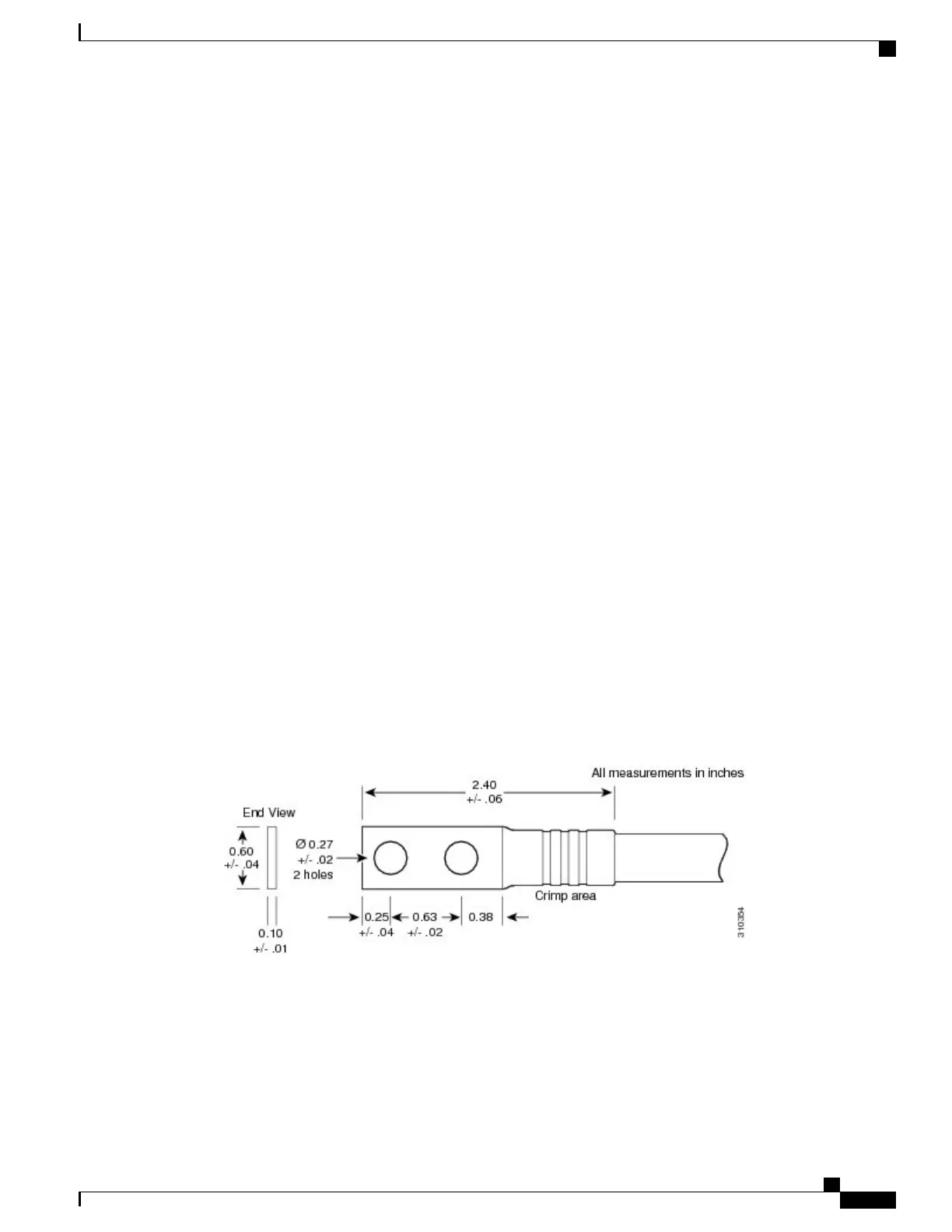
One 180-degree angle (straight) grounding lug that has two M6 bolt holes with 0.63 inches (5/8 inch)
(1.60 cm) of spacing center to center between them and a 6 AWG or larger multistrand copper wire.See
Figure 11: 180-Degree (Straight) Chassis Ground Lug, on page 19.
Figure 11: 180-Degree (Straight) Chassis Ground Lug
•
Two M6 hex head bolts and integrated locking washers are pre-installed on the chassis.
•
Cisco recommend at least 6 AWG multistrand copper ground cable. This cable is not available from
Cisco Systems; it is available from any commercial cable vendor. The cable should be sized according
to local and national installation requirements.
Cisco CRS Routers 16-Slot Line Card Chassis Enhanced Router Installation Guide
19
Installing Power Components
Installing the Chassis Ground Cable
 Loading...


