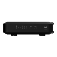
Chapter 3 Operation of Front Panel Indicators
Normal Operations (AC Power Applied)
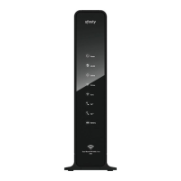
The following chart illustrates the appearance of the residential gateway front panel
LED status indicators during normal operations when AC power is applied to the
gateway.
Front Panel LED Status Indicators During Normal Conditions
Fr ont Panel Indica tor Normal Operations
1
POWER On
2
DS On
3
US On
4
ONLINE On
5
LINK
On - When a single device is connected to the Ethernet
port and no data is being sent to or from the residential
gateway
Blinks - When only one Ethernet device is connected and
data is being transferred between the consumer premise
equipment (CPE) and the wireless home gateway
Off - When no devices are connected to the Ethernet ports
6
USB
On - When a single device is connected to the USB port
and no data is being sent to or from the modem
Blinks - When only one USB device is connected and data
is being transferred between the consumer premise
equipment (CPE) and the wireless home gateway
Off - When no devices are connected to the USB ports
7
WIRELESS
ON/OFF
On - When the wireless access point is enabled and
operational
Blinks - When data is being transferred between the CPE
and the wireless home gateway
Off - When the wireless access point is disabled by the
user
8
WIRELESS
SETUP
Off - When wireless setup is not active
Blinks -
When wireless setup is active to add new wireless
clients on the wireless network
Note: In addition to the status shown in the previous table, some service providers
use color-coded LEDs to indicate detailed channel bonding and data link status. For
additional information about color-coded LEDs, check with your service provider.