© 2011 Cisco and/or its affiliates. All rights reserved. This document is Cisco Public Information. Page 3 of 12
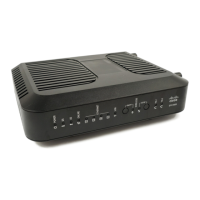
Figure 2. Cisco Model EPC3925 Front Panel (image may vary from actual product and specification)
Table 1. Front Panel Features
Power, DS, US, Online, Ethernet, USB, Wireless Link, Wireless Setup, Tel1, Tel2
Black, black lens, silver text
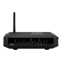
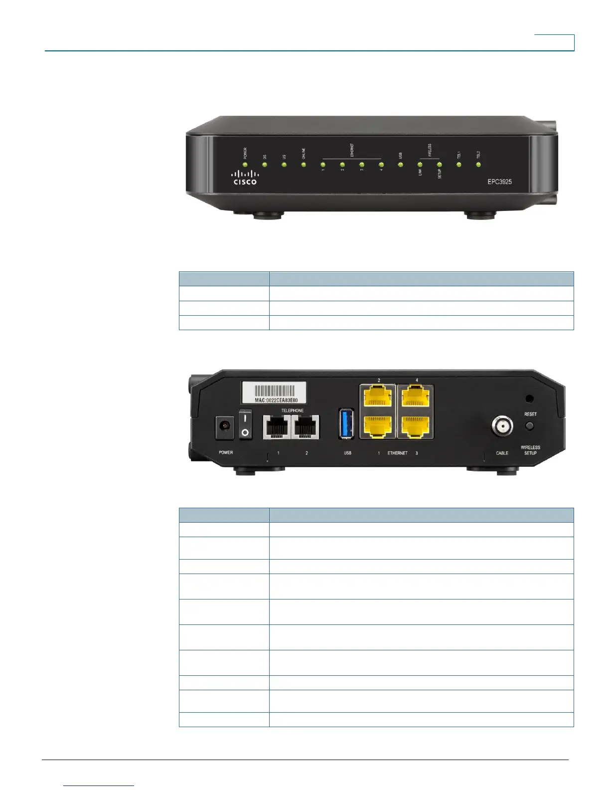
Figure 3. Cisco Model EPC3925 Back Panel (image may vary from actual product and specification)
Table 2. Back Panel Features
Switches power to the unit (power switch provided only on products carrying the CE mark)
POWER
Connector Color: Black
Connects modem to the DC output of the AC power adapter
Displays the MAC address of the cable modem
TELEPHONE 1 and 2
Color: Gray
RJ-11 telephone ports connect to home telephone wiring and to conventional telephones or fax
machines
Type 2 USB 2.0 port connects to a USB port on a printer or another USB device
ETHERNET (1 – 4)
Connector Color: Yellow
Four RJ-45 Ethernet ports connect to the Ethernet port on your PC or your home network
CABLE
Connector Color: White
F-connector connects to an active cable signal from your service provider
Activates WPS, which allows you to add wireless devices to the wireless network of the
residential gateway
(2) internal antennas provide a communication connection for the built-in 802.11n wireless
 Loading...