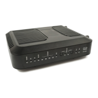
Back Panel Description
The following illustration identifies the back panel components on the DPC3928 and
EPC3928 residential gateways. Descriptions for each component follow the
illustration.
Important: Do not connect your PC to both the Ethernet and USB ports at the same
time. Your residential gateway will not function properly if both the Ethernet and
USB ports are connected to your PC at the same time.
1 ON/OFF SWITCH (Provided only on products that carry the CE mark)—
Allows you to turn off the residential gateway without removing the power cord.
Turning the residential gateway off using this switch ensures that the unit is
consuming no energy.
2 POWER—Connects the residential gateway to the AC power adapter that is
provided with your residential gateway.
Important: Use only the power supply provided with your residential gateway.
3 TELEPHONE 1 and 2—RJ-11 telephone ports connect to home telephone wiring
to conventional telephones or fax machines. (Products shipping in North
America support lines 1 and 2 on port 1 when used with a two-line phone.)
4 USB (Optional for some models)—Connects to selected devices. For models that
support USB, the default is one USB port.
5 ETHERNET—Four RJ-45 Ethernet ports connect to the Ethernet port on your PC
or your home network.
6 RESET—A momentary pressing (1-2 seconds) of this switch restarts (power
cycles) the device. Pressing and holding the switch for more than ten seconds
first causes a reset-to-factory-default of all settings and then restarts (power
cycles) the device.