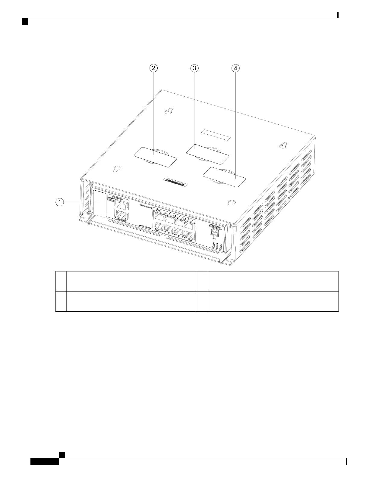
Figure 37: TELS Placement on the Rear Panel and Bottom of the FIPS Cover
TEL 2 on the bottom left of the FIPS cover over the
screw
2TEL 1 on the rear panel of the chassis1
TEL 4 on the bottom right of the FIPS cover over the
screw
4TEL 3 on the bottom center of the FIPS cover over
the screw
3
Step 7 Reinstall the chassis in the wall mount if you are using a mount. See Wall-Mount the Chassis, on page 32 for the
procedure.
Step 8 Attach the power cable to the chassis and connect it to an electrical outlet.
Step 9 Press the power switch on the rear panel.
Step 10 Check the power LED on the front panel. See Status LEDs, on page 11 for a description of the power LED. Solid green
indicates that the chassis is powered on.
Step 11 Place the chassis in FIPS mode.
See the following procedures for how to place the chassis in FIPS mode:
• See the "Security Certifications Compliance" chapter in the your software version configuration guide for the
procedure to enable FIPS mode.
Cisco Firepower 1010 Series Hardware Installation Guide
48
Installation, Maintenance, and Upgrade
Install the FIPS Opacity Shield

 Loading...