After rack-mounting and grounding the Firepower 2100, follow these steps to connect cables, turn on power,
and verify connectivity using the Firepower Management Center (FMC).
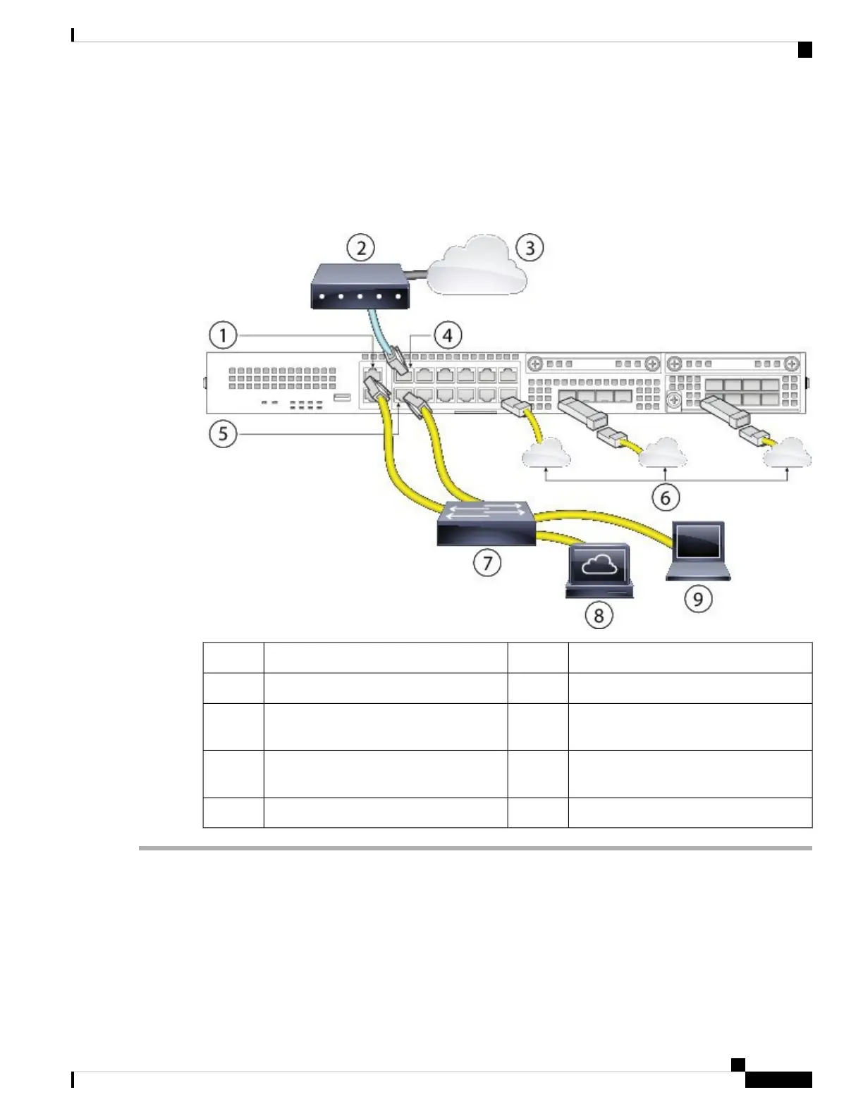
The following figure shows a simple topology using a Layer 2 switch. Your deployment will vary depending
on your basic logical network connectivity, ports, addressing, and configuration requirements.
Figure 44: Connect Cables to Firepower 2100 Interfaces
WAN modem2Management 1/1 (default 192.168.45.45)1
Ethernet 1/1 (outside DHCP from modem)4Internet3
Other data networks (SFP/SFP+
transceivers)
6Ethernet 1/2 (inside 192.168.45.1
management gateway)
5
Firepower Management Center
(192.168.45.44)
8Layer 2 switch7
Management computer (192.168.45.2)9
Step 1 Cable the following to a Layer 2 Ethernet switch:
• Ethernet 1/2 interface (outside)
• Management 1/1 interface (for the FMC)
• Local management computer
• FMC
Cisco Firepower 2100 Series Hardware Installation Guide
61
Mount and Connect
Connect Cables, Turn on Power, and Verify Connectivity Using Cisco Firepower Management Center

 Loading...


