EasyManuals Logo

Cisco Firepower 4110 Manual

Cisco Firepower 4110
26 pages
To Next Page IconTo Next Page
To Previous Page IconTo Previous Page
Page #12 background imageLoading...
Page #12 background image
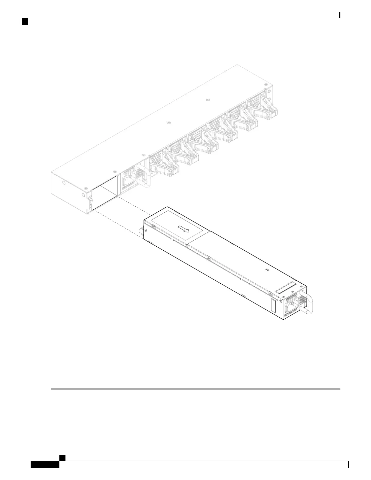
Figure 4: Remove the Power Supply Module
If the slot is to remain empty, install a blank faceplate to ensure proper airflow and to keep dust out of the chassis;
otherwise, install another power supply module.
Step 4 To replace a power supply module, hold the power supply module with both hands and slide it into the power supply
module bay.
Step 5 Push in the power supply module gently until you hear the latch engage and it is seated. Verify the power supply module
is operating correctly by checking the power supply module LED. See Power Supply Modules for a description of the
power supply module LEDs.
Installation, Maintenance, and Upgrade
12
Installation, Maintenance, and Upgrade
Remove and Replace the Power Supply Module

Other manuals for Cisco Firepower 4110

Questions and Answers:

Question and Answer IconNeed help?

Do you have a question about the Cisco Firepower 4110 and is the answer not in the manual?

Cisco Firepower 4110 Specifications

General IconGeneral
Power SupplyDual, hot-swappable
Form Factor1RU
Firewall Throughput (Multiprotocol)10 Gbps
Number of 10GE (SFP+) Interfaces8
Number of 40GE (QSFP+) Interfaces2
Redundant Power SupplyYes
Memory32 GB
Ports8 x 10GE, 2 x 40GE
Concurrent Sessions8 Million
Number of 10/100/1000 Interfaces8
Maximum Connections8 Million
Management Ports1 x RJ45
Data Ports8 x 10GE, 2 x 40GE
ProcessorIntel Xeon E5-2600

Related product manuals