EasyManuals Logo

Cisco Firepower 4110 Manual

Cisco Firepower 4110
26 pages
To Next Page IconTo Next Page
To Previous Page IconTo Previous Page
Page #17 background imageLoading...
Page #17 background image
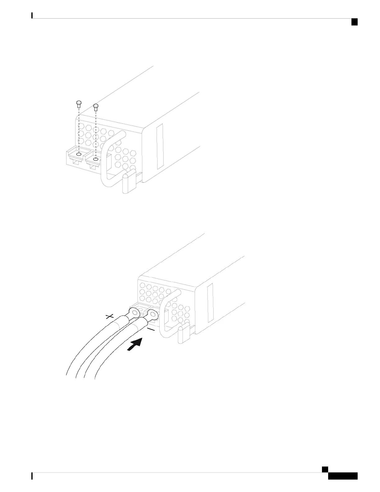
Figure 7: Remove the M5 Screws
Step 7 For easier cable management, insert the negative lead cable first. Replace the grounding lug with the cable in the
following order—wire terminal, then the screw with the captive washer.
Figure 8: Insert the Cables
Step 8 Tighten the M5 screw with the captive washer to the recommended torque of 5 in-lbs for the positive stud and wire.
Secure the wires coming in from the terminal block so that they cannot be disturbed by casual contact.
Installation, Maintenance, and Upgrade
17
Installation, Maintenance, and Upgrade
Connect the DC Power Supply Module

Other manuals for Cisco Firepower 4110

Questions and Answers:

Question and Answer IconNeed help?

Do you have a question about the Cisco Firepower 4110 and is the answer not in the manual?

Cisco Firepower 4110 Specifications

General IconGeneral
Power SupplyDual, hot-swappable
Form Factor1RU
Firewall Throughput (Multiprotocol)10 Gbps
Number of 10GE (SFP+) Interfaces8
Number of 40GE (QSFP+) Interfaces2
Redundant Power SupplyYes
Memory32 GB
Ports8 x 10GE, 2 x 40GE
Concurrent Sessions8 Million
Number of 10/100/1000 Interfaces8
Maximum Connections8 Million
Management Ports1 x RJ45
Data Ports8 x 10GE, 2 x 40GE
ProcessorIntel Xeon E5-2600

Related product manuals