Cisco 7010 and Cisco 7505 Chassis Replacement Instructions 3
Product Overview
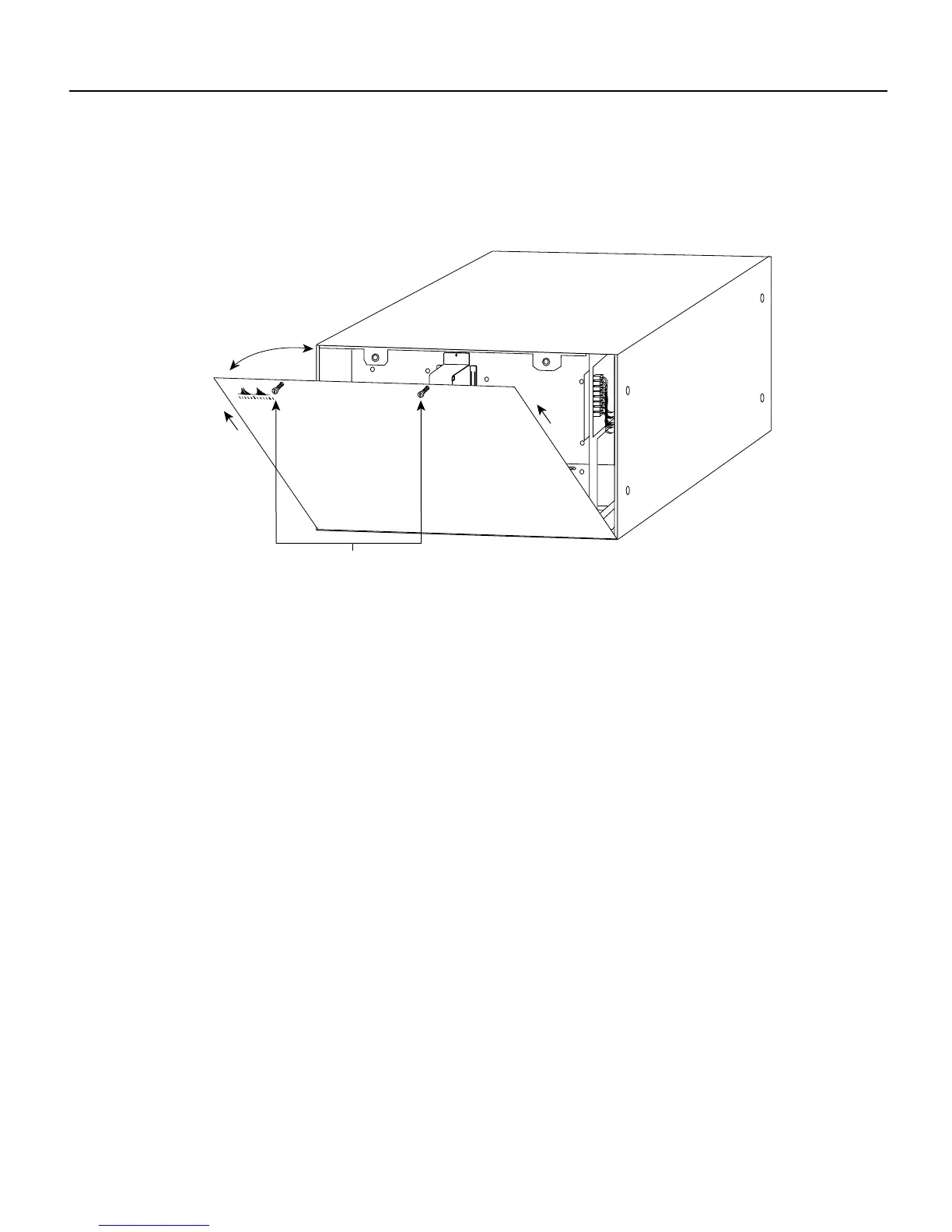
The removable chassis cover panel at the noninterface processor end of the router provides access
to the internal components. (See Figure 3.)
Figure 3 Chassis Cover Panel
Two captive slotted screws secure the chassis cover panel to the noninterface processor end of the
chassis. The cover shields against electromagnetic interference (EMI) and helps direct the flow of
cooling air through the chassis. Therefore, never operate the router with the cover removed.
For detailed descriptions of the system components, refer to the Cisco 7010 Hardware Installation
and Maintenance or Cisco 7505 Hardware Installation and Maintenance publications.
H2920
Captive screws