2 Cisco 7010 and Cisco 7505 Chassis Replacement Instructions
Product Overview
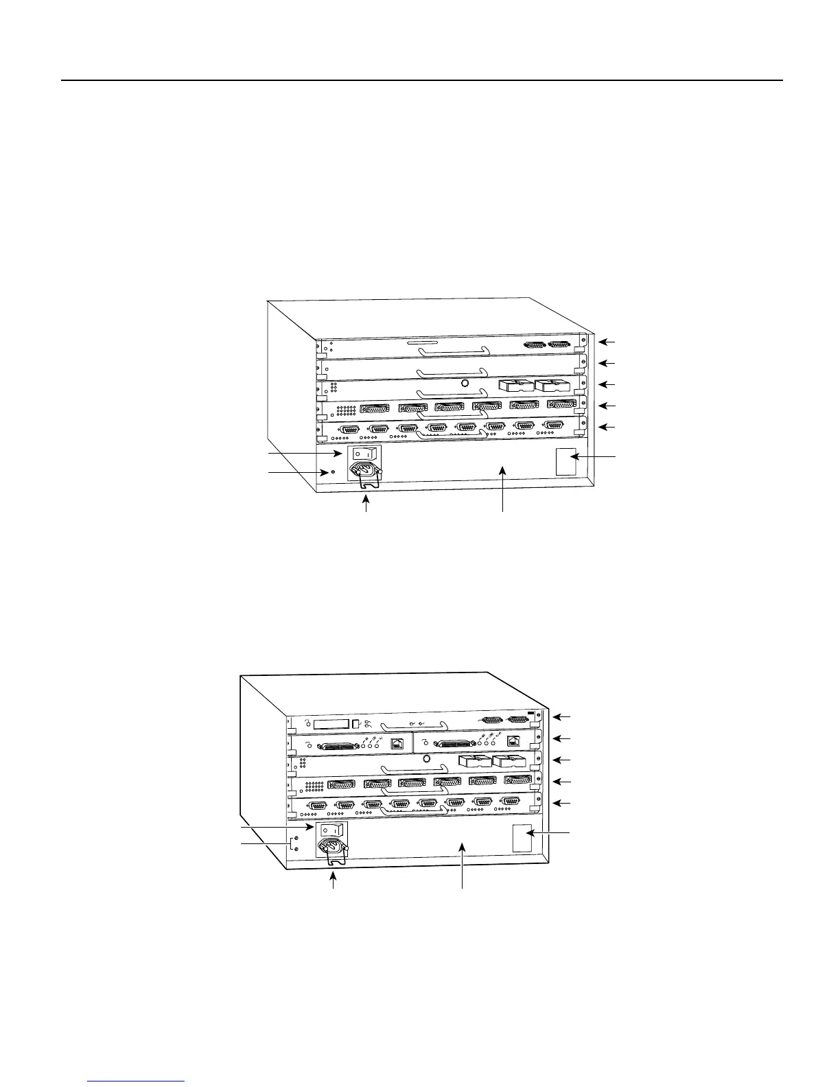
Product Overview
The Cisco 7010 is the five-slot model in the Cisco 7000 series. The Cisco 7010 provides three
interface processor slots. Figure 1 shows the interface processor end of the Cisco 7010. The Route
Processor (RP) and Switch Processor (SP) (or Silicon Switch Processor [SSP]), which are required
system components in all Cisco 7000 Series routers, occupy the two top slots. The remaining three
slots support any combination of interface types: Ethernet, Token Ring, FDDI, and so forth.
Figure 1 Cisco 7010—Interface Processor End
The Cisco 7505 is a five-slot model that provides four interface processor slots. Figure 2 shows the
interface processor end of the Cisco 7505. The Route Switch Processor (RSP1), which is a required
system component in the Cisco 7505 router, occupies the top slot. The remaining four slots support
any combination of interface types: Ethernet, Token Ring, FDDI, and so forth.
Figure 2 Cisco 7505—Interface Processor End
The interface processor end of the chassis also contains the AC power receptacle (a DC-input power
supply is also available, but not shown), the system power on/off switch, and the DC OK power
status LED, all of which are part of the power supply but accessible through cutouts in the chassis
frame. (See Figure 1 or Figure 2.) To the left of the power switch and receptacle cutout is the chassis
ground screw that provides a chassis ground connection for ESD equipment or a grounding wire.
H2359
RP slot
SP or SSP slot
Interface processor slot 1
DC OK LED
Power switch
Chassis ground
screw
Power receptacle
Interface processor slot 2
Interface processor slot 0
AC-input power supply
H2761
RSP slot
DC OK LED
wer switch
Chassis
grounding
receptacles
Power receptacle AC-input power supply
EJECT
SLOT 0
SLOT 1
NORMAL
CPU HALT
RESET
AUX.
CONSOLE
ROUTE SWITCH PROCESSOR
ENABLE
ENABLE
Interface processor slot 1
Interface processor slot 2
Interface processor slot 0
Interface processor slot 3