Cisco 7010 and Cisco 7505 Chassis Replacement Instructions 7
Prerequisites
Note If these conditions are not true, for instance, if you must remove a rack-mounted chassis
before you can install the new chassis, you must disconnect all power and network interface cables.
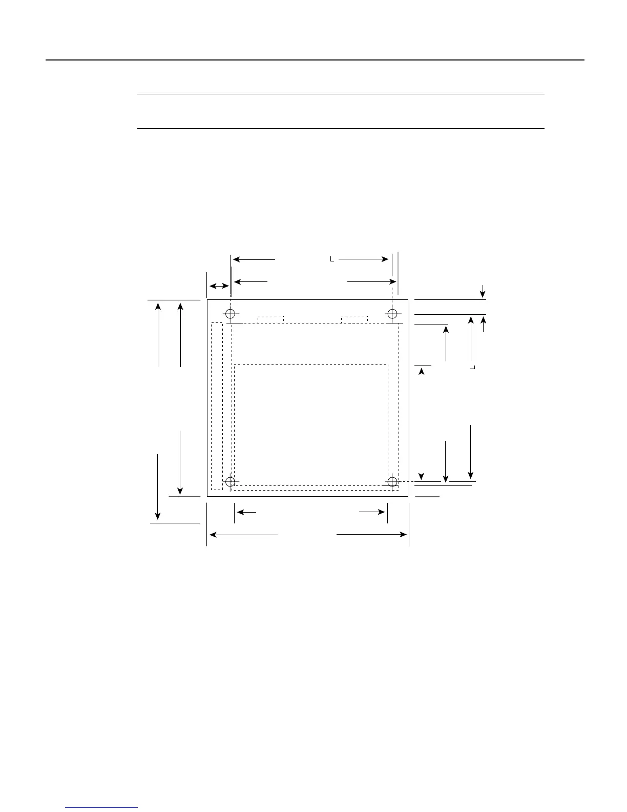
Also, ensure that your new chassis allows sufficient clearance for maintenance: to remove and
replace processor modules and interface cables at the interface processor end, and to access the
internal components at the noninterface processor end. Figure 4 shows the chassis footprint and the
clearance required to remove or install each of the major components.
Figure 4 Chassis Footprint and Clearance Requirements for Maintenance
Noninterface processor end
Chassis foot C
14.25 in. (36.20 cm)
Chassis width
17.50 in. (44.45 cm)
Fan tray
Chassis depth
17.0 in. (43.18 cm)
Chassis depth with power cord and cable
management bracket
19.0 in. (48.26 cm)
Interface processor width
14.55 in. (36.96 cm)
Power supply width
14.60 in. to ears (37.08 cm)
Interface processor depth
11.25 in. (28.58 cm)
Power supply depth
12.00 in. (30.48 cm)
1.25 in. (3.18 cm)
Interface processor end
H2818
2 in.
(5.08 cm)
Chassis foot C
13.32 in. (33.83 cm)