4
Caution If the rack is on wheels, ensure that the brakes are engaged or that the rack is otherwise stabilized.
Note We recommend that you maintain a minimum air space of 6 inches (15 cm) between walls and the chassis air vents and
a minimum horizontal separation of 12 inches (30.5 cm) between two chassis to prevent overheating.
The installation hardware is not suitable for use with racks with obstructions (such as a power strip) that could impair access
to field-replaceable units (FRUs).
Warning
To prevent bodily injury when mounting or servicing this unit in a rack, you must take special precautions to ensure
that the system remains stable. The following guidelines are provided to ensure your safety:
>If it is the only unit in the rack, this unit must be mounted at the bottom of the rack.
>When mounting this unit in a partially-filled rack, load the rack from the bottom to the top with the heaviest
component at the bottom of the rack.
>If the rack is provided with stabilizing devices, install the stabilizers before mounting or servicing the unit in the
rack.
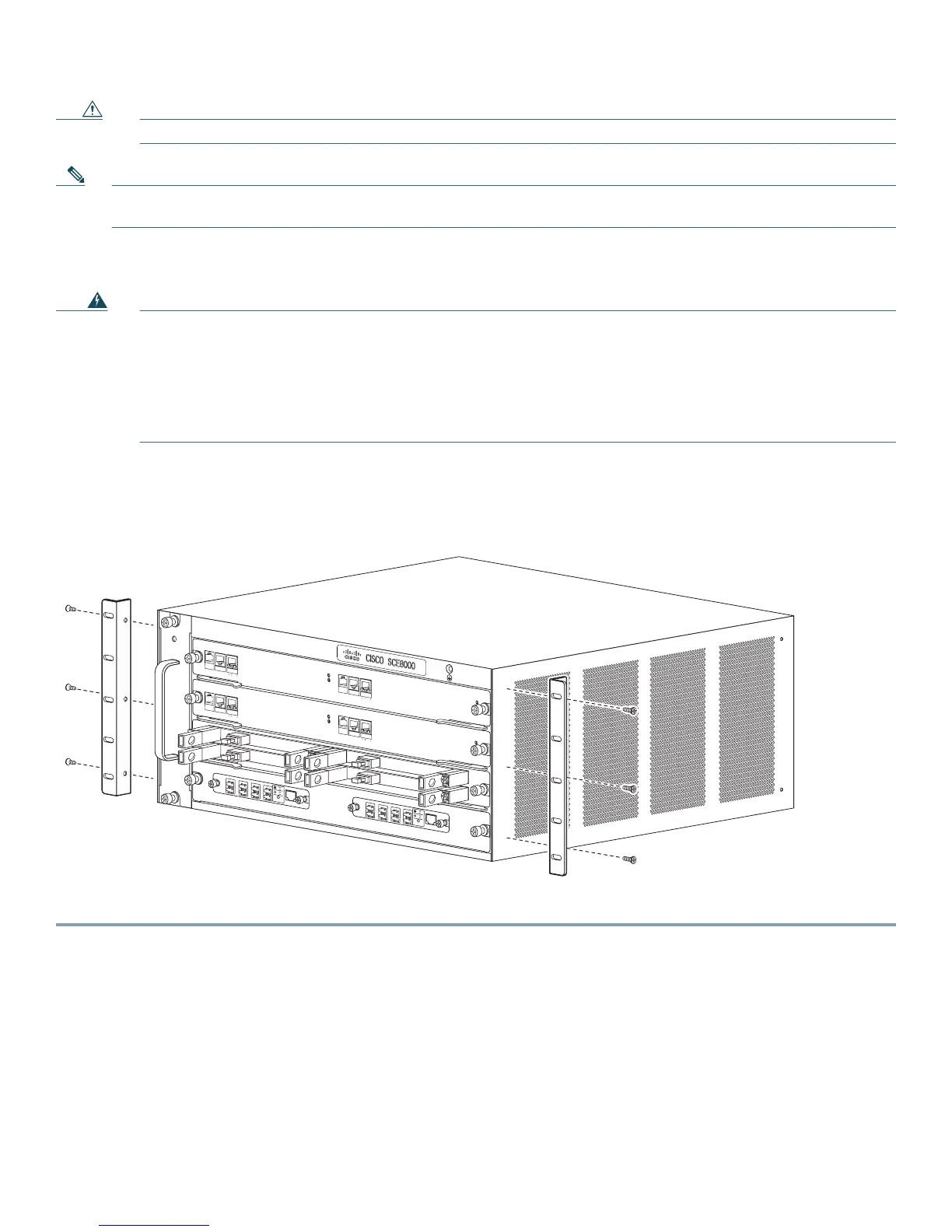
The chassis is shipped with the mounting brackets installed on the front of the chassis. You can remove these brackets and install
them on the rear of the chassis, using the holes provided in the rear side of the chassis (Figure 1).
Figure 1 Cisco SCE 8000 Chassis Brackets
Step 1 Position the chassis in the rack as follows. If the:
• Front of the chassis (front panel) is at the front of the rack, insert the rear of the chassis between the mounting posts.
• Rear of the chassis is at the front of the rack, insert the front of the chassis between the mounting posts.
Step 2 Align the mounting holes in the bracket (and optional cable guide) with the mounting holes in the equipment rack.
Step 3 Use a tape measure and level to choose and mark the position that the chassis is to be installed in the rack. Make a mark
at equal height on both sides of the rack. This helps ensure that the chassis is installed straight and level (Figure 2).
FAN S
T
A
TU
S
SCM
1
SCM
2
SIP
3
4
SCE
8000
-F
AN
SYS
T
E
M
PO
W
E
R
O
P
TI
C
A
L
BYPAS
S
S
TA
TU
S
AUX
POR
T
2
LINK
ACTI
V
E
MASTE
R
SCE80
00 EX
T
E
N
DED
SERVIC
E
CON
T
R
O
L
M
O
DUL
E
OPTIC
A
L
B
YP
A
SS
OP
T
ICA
L
BY
P
ASS
C
ON
S
OL
E
1
0
1
0
0
1
0
0
0
LI
NK
A
CTIVE
PO
R
T1
A
C
A
B
C
D
B
D
S
TA
T
U
S
C
T
R
L
OPB
-
SCE8
K-MM
O
P
TICA
L
B
Y
PA
SS
1
T
X
R
X
T
X
R
X
T
X
R
X
T
X
R
X
A
C
A
B
C
D
B
D
S
T
A
T
U
S
C
T
R
L
OP
B
-S
CE
8
K
-
M
M
OPT
ICAL B
YP
ASS
2
T
X
R
X
T
X
R
X
T
X
R
X
TX
RX
S
Y
ST
E
M
P
O
W
E
R
O
P
TI
C
A
L
B
Y
PA
S
S
S
TA
TU
S
AU
X
P
OR
T
2
1
0
100
1
0
0
0
L
INK
A
C
TI
V
E
M
A
S
T
ER
SCE80
00 EX
T
E
N
D
ED
SERVIC
E
CON
T
R
O
L
M
O
DUL
E
S
C
E8
00
0-
SC
M
-E
S
C
E8
00
0-
SC
M
-E
SC
E8
00
0-S
IP
C
ON
S
OL
E
1
0
1
0
0
1
0
0
0
LI
NK
A
CTI
VE
PO
R
T
1
O
PT
I
C
A
L
B
YP
A
SS
OP
TI
C
A
L
BY
P
ASS
S
T
A
T
U
S
AC
T
I
V
E
/
L
I
N
K
S
PA
-
1
X
1
0
G
E
-L
-
V
2
S
TATU
S
ACTI
VE/
LIN
K
S
PA
-
1
X
1
0
G
E
-L
-
V
2
S
T
A
TU
S
AC
T
I
V
E
/
L
I
NK
S
PA-
1
X
10GE-
L
-
V
2
S
T
A
T
US
A
C
T
I
V
E
/
LI
NK
S
PA-
1
X
1
0GE-
L
-
V
2
1
0
100
1
0
0
0
270890