78-20007-03 MX200 Table Stand Installation Sheet | 2012 JANUARY | © 2011-2012 Cisco Systems, Inc. All rights reserved.
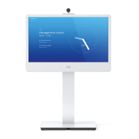
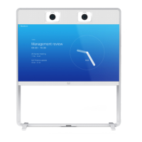
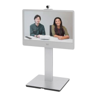
Installing Cisco TelePresence MX200 - Table Stand
3
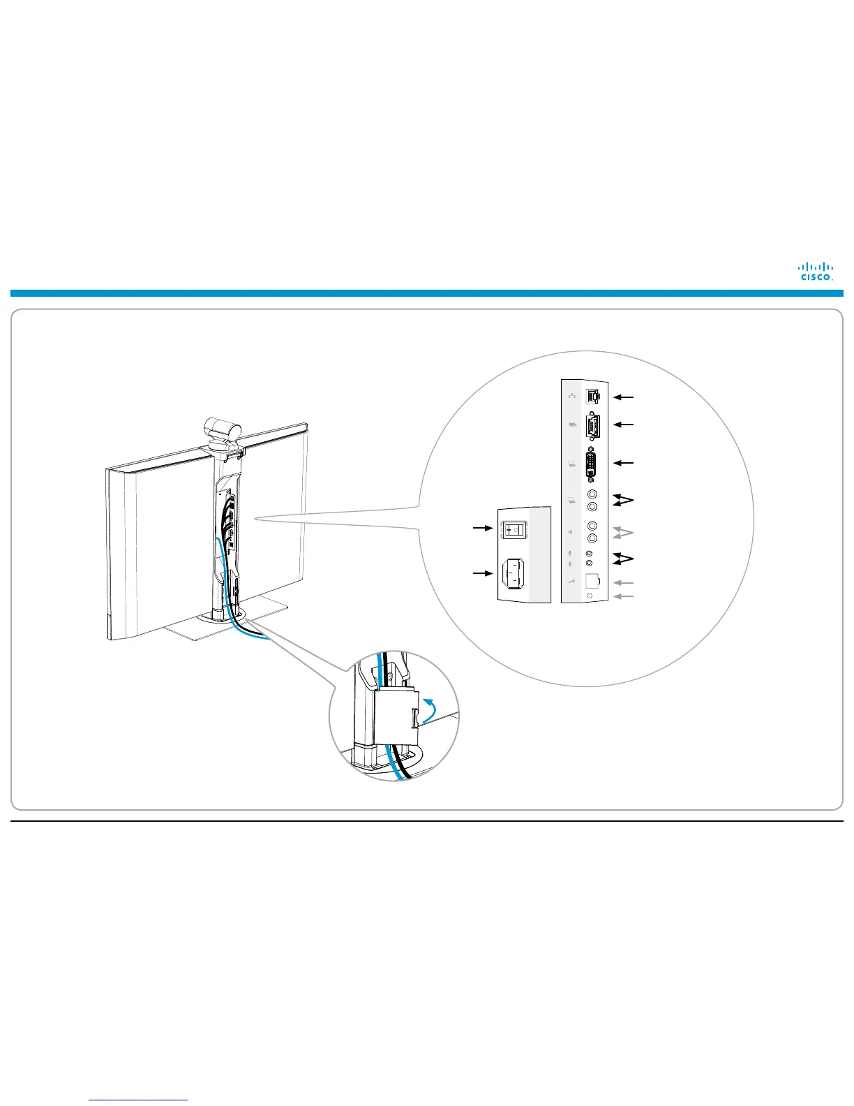
Connecting the cables
i Connect the cables.
The connectors are placed at the rear side of the
LCD video unit. See details to the right.
ii Lead the cables downward and out at the back of
your system.
LCD video unit connectors
Power
supply
Touch controller
Local area
network (LAN)
PC audio input
PC video input
Audio line output
(cable not included)
Microphones
(one default, second optional)
Reset factory settings
iii Snap on the cable channel lid for strain relief.
Note: When you position the cables side by side it
is easier to snap on the lid.
 Loading...