Citrix ADC MPX
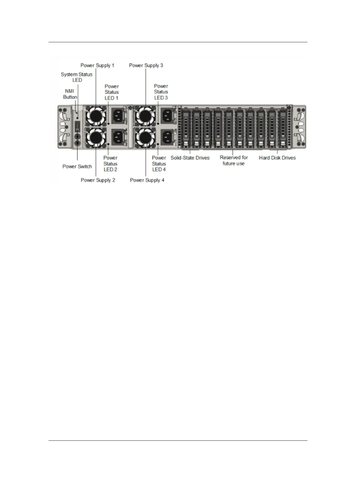
The following components are visible on the back panel of the MPX 22040/22060/22080/22100/22120
appliance:
• Non‑maskable interrupt (NMI) Button, used at the request of Technical Support to initiate a core
dump. To press this red button, which is recessed to prevent unintentional activation, use a pen,
pencil, or other pointed object. The NMI Button is also available remotely over the network in
the LOM GUI, in the Remote Control menu. For more information, see Lights out management
port of the appliance topic.
• System status LED, which indicates the status of the appliance, as described in Common hard‑
ware components.
Note: On an MPX 22040/22060/22080/22100/22120 appliance running LOM firmware version
3.22, the system status LED indicates an error (continuously glows RED) even though the appli‑
ance is functioning properly.
• Four power supplies, each rated at 750 watts, 100–240 volts. A minimum of two power supplies
are required for proper operation. The extra power supplies act as backup. Each power supply
has an LED that indicates the status of the power supply, as described in Common hardware
components.
• Power switch, which turns o power to the appliance. Press the switch for less than two seconds
to shut o the power.
• Two 128 or larger GB removable solid‑state drives.
• One 500 GB or larger removable hard disk drive that is used to store user data.
Note: Drive densities might increase as components become EOL but its size is never smaller than the
original.
© 1999–2023 Cloud Soware Group, Inc. All rights reserved. 78
 Loading...