PF-F/PFU Series
Model No.
Dimension D
PF8000F 40 mm
PF16000F 50 mm
Mounting, installation and adjustment
■
Do not use a load that can produce surge voltage. When
directly running the load that generates a surge such as
relay and solenoid valve, use a surge absorbing element
built-in. If there is a surge source on the same power
supply line, similarly implement surge protection.
■
This product has no protection against lightning surge.
This product is CE marking compliant but has no protection
against lightning surge. For the protection against lightning
surge, take countermeasures on the equipment side
.
■
Make sure that the lead wire is free of repeated
bends and tension. This may lead to disconnection.
■
Use the accessory cable (3 m). When extending the
cable, contact your CKD branch or dealer.
■
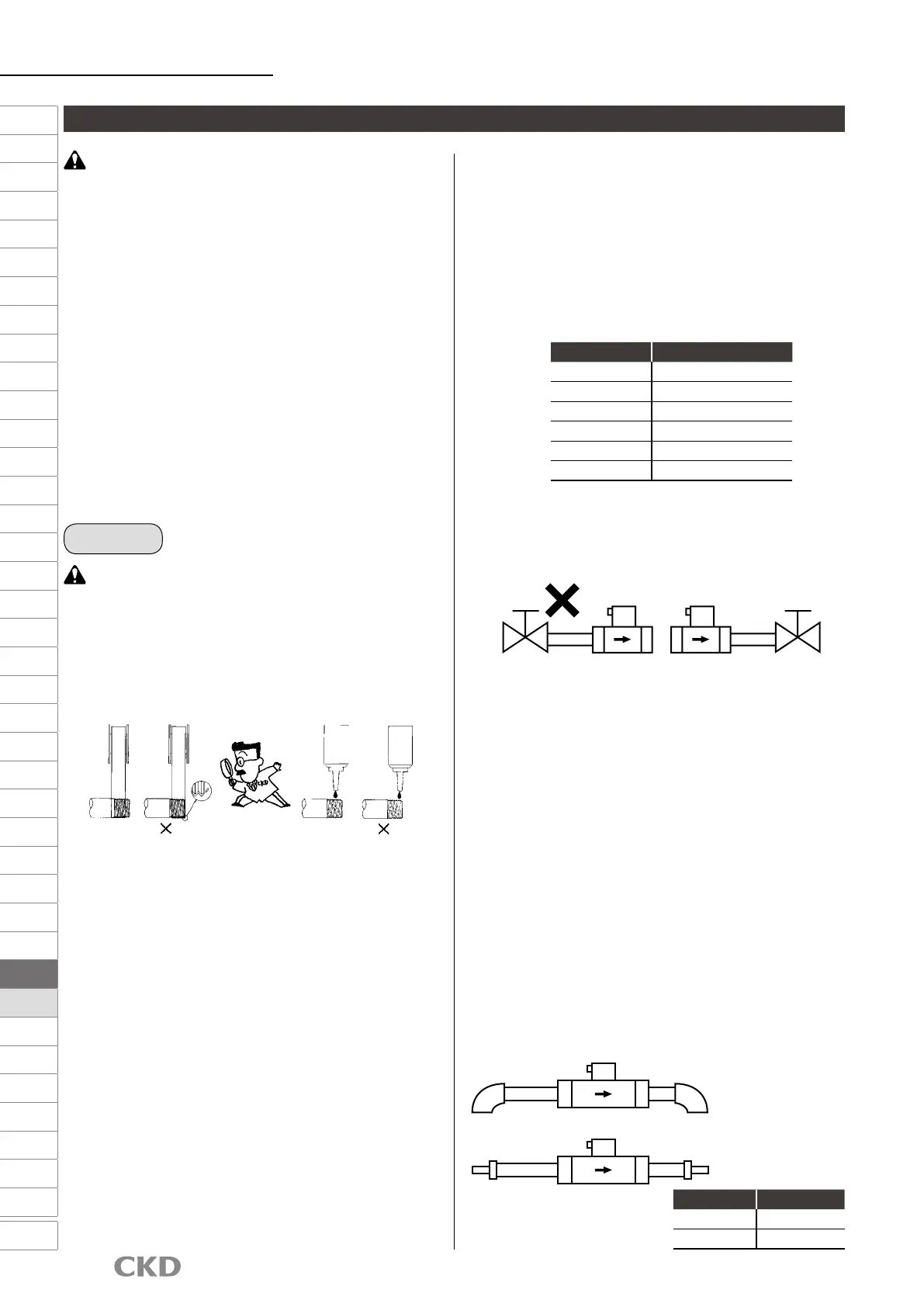
When connecting pipes, wrap sealing tape in the
opposite direction from the threading, from the
inside position to within 2 mm from the pipe end.
●
If sealing tape protrudes from the pipe threads, it could be
cut when screwing the bolts in. This could cause the tape
to enter the product, causing failures.
●
When using a liquid sealant, make sure it does not
adhere to resin parts. Otherwise resin parts could be
damaged, which is dangerous.
■
Check that the piping connected to the pneumatic
components is not dislocated due to vibration,
looseness, or tension.
●
Piping dislocation is dangerous.
■
Observe the following precautions when using
nylon tubes or urethane tubes for piping material.
●
Use ame-resistant tubes or metal steel pipes in an
environment where spattering may occur.
●
When using the standard push-in tting on the spiral tube,
x the base of the tube with a hose clamp. Rotation may
occur, causing a reduction in holding force.
■
Connect piping so that connections are not
dislocated by equipment movement, vibration, or
tension.
■
Always ush just before piping pneumatic components.
●
Any foreign matter that has entered the pipes during
piping must not enter the pneumatic components.
■
Use appropriate torque to tighten the pipes when
connecting them.
●
The purpose is to prevent air leakage and damage to bolts.
●
First tighten the bolts by hand to ensure that the threads
are not damaged, then use a tool.
■
When adjusting the ow rate using a metering valve (glove
valve, ball valve, etc.), install the metering valve on the
secondary side (downstream side) of the sensor.
Generated drift (turbulence in the ow) could cause errors
.
■
Do not install the regulator immediately before the
sensor. Generated drift may cause errors.
●
When installing the regulator on the primary side, provide
a straight piping section of 10D and over.
* Where "D" indicates the inner diameter of the piping
material.
●
Select a regulator that has sufcient margin of ow
characteristics for the max. ow rate of the sensor.
■
Align the uid ow direction to the direction indicated
on the sensor when connecting the pipes. When
connecting it in reverse, the larger value is displayed.
■
When using an elbow or bush in the piping, it is
recommended to provide straight piping sections of
10D and over on the primary side and 5D and over
on the secondary side.
●
For PF8000F/PF16000F Series, be sure to provide
straight piping sections.
●
Bore size change by bush should be limited to one size.
3. Piping
CAUTION
CAUTION
[Recommended values]
Port thread
Tightening torque N·m
Rc3/8 22 to 24
Rc1/2 28 to 30
Rc3/4 31 to 33
Rc1 36 to 38
Rc1 1/2 48 to 50
Rc2 54 to 56
Solid
liquid
sealant
Solid
liquid
sealant
OK OK
OK
When using bush tting
5D
10D
When using elbow tting
5D
10D
F.R.L
F (Filtr)
R (Reg)
L (Lub)
PresSW
Shutoff
SlowStart
FlmResistFR
Oil-ProhR
MedPresFR
No Cu/
PTFE FRL
Outdrs FR
F.R.L
(Related)
CompFRL
LgFRL
PrecsR
VacF/R
Clean FR
ElecPneuR
AirBoost
SpdContr
Silncr
CheckV/
other
Jnt/tube
AirUnt
PrecsCompn
Mech/
ElecPresSw
ContactSW
AirSens
PresSW
Cool
AirFloSens/
Contr
WaterRtSens
TotAirSys
(Total Air)
TotAirSys
(Gamma)
RefrDry
DesicDry
HiPolymDry
MainFiltr
Dischrg
etc
Ending
1390
 Loading...