MJE-PPX No.0040-81V
INSTRUCTION MANUAL
PARECT PRESSURE SWITCH
PPX series
Read this instruction manual carefully before using this product, particularly the section
describing safety.
Retain this instruction manual with the product for further consultation whenever necessary.
Precaution
● This product is designed for air / non-corrosive gas.
●
● Do not touch electric wiring connections (bare live parts): this will cause an electric shock.
During wiring, keep the power off. Also, do not touch these live parts with wet hands.
● A product intended for use in Japan conforms to the Japanese Measurement Act.
Do not use a product intended for use overseas in Japan.
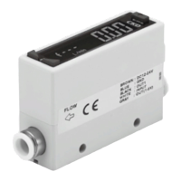
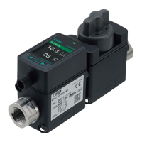
1 PART DESCRIPTION
㸯
Connection
connector
Pressure port
6M type: R
1
/
8
+ M5 female screw
6G type: G
1
/
8
+ M5 female screw
6N type: NPT
1
/
8
+ M5 female screw
PPX
Output 1 operation
indicator
Lights up when com-
parative output 1 is ON
Mode selection key
Unit display
(Note 1, 2)
Main display
Sub display
Setting value
DOWN key
Setting value UP key
Output 2 / analogue
voltage / current out-
put operation indicator
Standard type:
Lights up when com-
parative output 2 is ON
High-function type:
Lights up when analogue
voltage / current output is set
Notes: 1) In the case of a model that is intended for use outside Japan, attach the unit switch plate corresponds to the set
pressure unit.
2) The product for use inside Japan can be set only to “MPa” or “kPa.”
2 PIPING
● When connecting a commercial coupler to the pres-
sure port, attach a 12mm spanner (14mm for 6G
type) to the pressure port’s hexagon section to fix
the port, and then tighten with a tightening torque of
9.8N·m or less (M5 female: 1N·m or less). The com-
mercial coupler or pressure port section will be dam-
aged if the tightening torque is excessive.
Wrap sealing tape around the coupler when connect-
ing to prevent leaks.
12mm spanner
3 MOUNTING
● The sensor mounting bracket PPX-KL is available as an option. When mounting the sensor
onto the sensor mounting bracket, etc., the tightening torque should be 0.5N·m or less.
M3 (length 6mm) screws
with washers
(Accessory with PPX-KL)
Sensor mounting bracket
PPX-KL (Optional)
● The panel mounting bracket PPX-KHS (optional), as well as the front cover PPX-KCB
(optional) are also available.
● For mounting of the panel mounting bracket, refer to the Instruction Manual en-
closed with PPX-KHS.
4 WIRING
Connection method
● Insert the cable with connector PPX-C□ into
this product’s connection connector section
Disconnection method
● Pressing the release lever of the cable with
connector, pull out the connector.
Cable with connector
PPX-C□
Release lever
<Recommended product>
Contact: SPHD-001T-P0.5
Housing: PAP-04V-S
[JST Mfg. Co., Ltd.]
Note:
Do not pull by holding the cable without pressing the release lever, as this can cause cable break or connector break.
<Connection connector pin arrangement>
1 2 3 4
Connector pin No.
Terminal name
1 +V
2 Comparative output 1
3
Standard type: Comparative output 2
High-function type: Analogue voltage / current output or external input
4 0V
5 I/O CIRCUIT DIAGRAMS
NPN output type
Standard type
Main circuit
(Brown) +V
(Black)
Comparative output 1
(White) Comparative output 2
(Blue) 0V
Load
Load
100mA max.
100mA max.
+
12 to 24V DC
±10%
-
High-function type
Main circuit
(Brown) +V
(White)
Analogue voltage / current output
or external input (Notes 1, 2, 3)
(Black)
Comparative output 1
(Blue) 0V
Load
100mA max.
5V
1kΩ
+
12 to 24V DC
±10%
-
PNP output type
Standard type
Main circuit
(Brown) +V
(Black) Comparative output 1
(White)
Comparative output 2
(Blue) 0V
Load
Load
100mA max.
100mA max.
+
12 to 24V DC
±10%
-
High-function type
Main circuit
(Brown) +V
(White)
Analogue voltage / current output
or external input (Notes 1, 2, 3)
(Black)
Comparative output 1
(Blue) 0V
Load
100mA max.
1kΩ
+
12 to 24V DC
±10%
-
Notes: 1) When the analogue current is output, the output load resistance should be 250Ω max.
2) Take care that when the analogue current is output, 5V or more voltage generates.
3) When using the analogue voltage output, be careful to the input impedance of the connected device.
Furthermore, note that if the cable is extended, the cable resistance will cause the voltage to drop.
6 OUTPUT MODE AND OUTPUT OPERATION
● The EASY mode, hysteresis mode or window comparator mode can be selected as
the output mode for comparative output 1 and comparative output 2.
Refer to <Comparative output 1 / 2 output mode setting> in “
8
MENU SET-
TING MODE” for details.
EASY mode
● ON / OFF of the comparative output is controlled in this mode.
Pressure
P
0
ON
OFF
Comparative
output
H (Hysteresis)
Notes: 1)
Refer to in “
9
PRO MODE” for setting.
2) “
” is displayed for comparative output 1 and “ ” for comparative output 2 on the sub-display.
Hysteresis mode
● The comparative output ON / OFF state can be controlled with randomly set hyster-
esis in this mode.
0
Pressure
Comparative
output
H (Hysteresis)
Hi
Lo
ON
OFF
H: 1digit or more
2 digits or more when
using psi unit
Note: “ ” or “ ” is displayed for comparative output 1 and “ ” or “ ” for comparative output 2 on the
sub-display.