EasyManua.ls Logo

CKD FLUEREX PF Series - User Manual

Default Icon
22 pages
To Next Page IconTo Next Page
Loading...
Flow sensor for compressed air PF Series
Strongly supports energy-saving activitiesStrongly supports energy-saving activities
Integrating flow and instantaneous flow rate displays can be
switched with a single operation
.
Correction of pressure/temperature is not required.
·
No need for pressure correction = Due to the mass detection
method used, there is no effect due to pressure change.
Hence, pressure correction is not required.
Displays the flow rate converted to atmospheric pressure (1 atm).
·
No need for temperature correction = Fluid temperature
is detected by the platinum thin film temperature sensor,
and is always displayed after being converted to flow
rate at 0°C.
·Maintenance and measurement of air quality
available in one unit.
·Piping space/piping processes
can be reduced.
3/8
(10)
1/2
(15)
3/4
(20)
1
(25)
1
1
/
2
(40)
Port size Rc
Module
Standard
PFU1000F
PFU2000F
PFU500F
PF16000F
PF8000F
PF4000F
PF2000F
PF1000F
PF500F
2
(50)
0 10 100 1000 10000 100000
25 500
50 1000
100 2000
200 4000
400 8000
800 16000
25 500
50 1000
100 2000
Flow rate range L/min(normal)
Model
Series
Secure design that is hard to break even with drain (water drops)
(double the environment-resistance compared to conventional products)
·Improved water resistance by applying
a special coating to the platinum thin-film sensor.
·Overheating of the sensor element is prevented
by a protection circuit.
Reliable
Easy to use
Easily visible LED is used. Integrating flow 5-digit display.
High performance
Digital direct-reading, correction not needed
The display and sensor are housed in one compact body.
A wide range of output variations
Filter and regulator are integrated
into a unit by modular design
(PFU500F,PFU1000F,PFU2000F)
Unrestricted installation
Heavy duty design
Degree of protection IP64 equivalent
Flow distribution is constant
Flow rate distribution leans towards the outer circumferential direction
due to the elbow.
Rectifier
Sensor
Air
High precision of practical precision ±3% F.S.
Pressure loss 0.005 MPa (primary pressure: 0.7 MPa)
is realized
*1
By laminating the rectification filter,
pressure loss is reduced to 0.005 MPa.
(*1: Applicable models only)
Straight piping section not required
*2
Thanks to the rectifier, there is no impact even if the elbow and
T-shaped socket are piped just before the sensor.
(*2: Excluding PF8000/PF16000F)
With no need for correction, practical precision ±3% F.S. is realized at
temperature 0 to 40°C and pressure 0.1 to 1.0 MPa.
Pipes can be installed in any orientation, vertical,
horizontal, etc.
·
The display unit can be rotated up to 270° as desired.
·Connector wires can be drawn out along the piping
and do not occupy space.
·Connector wires can be drawn from either IN or OUT
side by rotating the connector case 180°.
OUT
TOTAL
H
L
FLOW SENSOR PF
SERIES
FLUEREX
L/min(normal)
Connector case
FLUEREX
L/min
PF
SERIES
FLOWSENSOR
TOTAL
OUT
H
L
Analog output
Pulse output
4 to 20 mADC
0 to 5 VDC
1 to 5 VDC
0 to 10 VDC
Switch output
Standard
Standard
Option
Option
Option
Option
Measure the status of flow rate
Consider countermeasures
Plan
Grasp the current situation
Do
Implement measures
Action
Correction/continuation
Check
Effect confirmation
Measurement with flow rate sensor
Cost conversion is possible using integrating function
Standardization of equipment/line consumption
Application in other lines
Stop the air pressure supply during non-operation
Blow time reduction
Application of energy saving nozzle
Lower pressure
Very useful in grasping the current situation and confirming the effect of energy
It can be safely used even in harsh environments
such as dust and water splashing from all directions.
F.R.L
F (Filtr)
R (Reg)
L (Lub)
PresSW
Shutoff
SlowStart
FlmResistFR
Oil-ProhR
MedPresFR
No Cu/
PTFE FRL
Outdrs FR
F.R.L
(Related)
CompFRL
LgFRL
PrecsR
VacF/R
Clean FR
ElecPneuR
AirBoost
SpdContr
Silncr
CheckV/
other
Jnt/tube
AirUnt
PrecsCompn
Mech/
ElecPresSw
ContactSW
AirSens
PresSW
Cool
AirFloSens/
Contr
WaterRtSens
TotAirSys
(Total Air)
TotAirSys
(Gamma)
RefrDry
DesicDry
HiPolymDry
MainFiltr
Dischrg
etc
Ending
1368
Discontinue
Question and Answer IconNeed help?

Do you have a question about the CKD FLUEREX PF Series and is the answer not in the manual?

CKD FLUEREX PF Series Specifications

General IconGeneral
Material (Sleeve)POM
Material (Release Ring)POM
TypeFitting
Applicable TubingNylon, Polyurethane
Material (Seal)NBR
Material (Chuck)Stainless Steel
Thread TypeNPT
Operating Pressure Range0 to 1.0 MPa
Applicable FluidAir, Water
SeriesFLUEREX PF
Port Size1/8 to 1/2 inch

Summary

High performance features

High precision of practical precision ±3% F.S.

Achieves practical precision ±3% F.S. at 0-40°C and 0.1-1.0 MPa without correction.

Low pressure loss

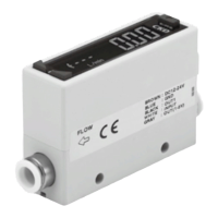
Pressure loss of 0.005 MPa realized by laminating a rectification filter.

Reliable design and protection

Heavy duty design

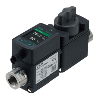
Secure design resistant to drain and improved water resistance via special coating.

Degree of protection IP64 equivalent

Safely usable in harsh environments with dust and water splashing.

Ease of use and installation

Digital direct-reading, correction not needed

Displays flow rate converted to atmospheric pressure; no pressure or temperature correction required.

Unrestricted installation flexibility

Pipes can be installed in any orientation; display unit is rotatable.

Integrated unit design

Applications of Flow Sensor

Flow rate management examples

Used for managing flow in various industrial lines and equipment.

Functional explanation

PF500 F to PF4000 F Series Specifications

Accuracy and linearity

Specifies accuracy ±1.5% F.S. for linearity and ±2.0% F.S. for temperature characteristics.

Pressure loss and response time

Details pressure loss of 0.005 MPa or less and response time of 2.5 seconds.

How to order PF500 F to PF4000 F Series

Model selection codes

Explains codes for flow rate range, port size, output type, and bracket options.

Internal structure and parts list

Pressure loss characteristics graphs

Dimensions PF500 F to PF4000 F Series

PF8000 F;PF16000 F Series Specifications

Flow rate range and port size

Specifies flow rate ranges (0.40-8.00, 0.80-16.00 m³/min) and port sizes (Rc1 1/2, Rc2).

Accuracy and working conditions

Details accuracy ±2.5% F.S. for PF8000F and ±1.5% F.S. for PF16000F.

How to order PF8000 F;PF16000 F Series

Internal structure and parts list PF8000 F;PF16000 F Series

Dimensions PF8000 F;PF16000 F Series

PFU500 F to PFU2000 F Series Specifications

Flow rate range and port size

Specifies flow rate ranges (25-500, 50-1000, 100-2000 L/min) and port sizes (Rc3/8, Rc1/2).

Accuracy and working conditions

Details accuracy ±1.5% F.S. for linearity and ±2.0% F.S. for temperature characteristics.

How to order PFU Series

Connection module and option codes

Explains selection of connection modules (W3000-10, W4000-15) and options like flow direction.

Dimensions PFU Series

Electric wiring: Analog output

Load resistance requirements

Specifies minimum load resistance for different analog output types to ensure correct operation.

Electric wiring: Integrated pulse output

Electric wiring: Output connection examples

Analog output connection examples

Shows connections for relay/recorder, programmable controller, and receiver for analog outputs.

Operations: Display and output indicators

Unit lamps and displays

Details the [L] and [H] unit lamps for integrating flow and the 5-digit display for instantaneous/integrating flow.

Switch output parameters

Describes setting parameters (0, 1, 2) for switch output detection of disconnection errors, flow rate errors, and integrating flow thresholds.

Hysteresis and clearing integrating flow

Explains setting hysteresis to prevent chatter and clearing the integrating flow value.

Functions and operations for monitor

Measurement mode

Describes how to view instantaneous and integrating flow rates, and how to switch between them.

Write mode operations

Guides on setting parameters, low/high values, hysteresis, and clearing integrating flow.

Safety Precautions

Checking specifications and fluid compatibility

Warns against using flammable fluids and using the product outside specified conditions.

Design by application and environment

Notes on air leakage tolerance and avoiding explosive gas atmospheres.

Working environment considerations

Advises on using the product within specific temperature ranges and avoiding corrosive environments.

Product-specific cautions

Mounting and installation cautions

Advises on proper installation, avoiding vibration, and handling pneumatic components.

Pre-operation confirmation

Emphasizes checking pipe connections for leaks and keeping cables away from noise sources.

Mounting, installation and adjustment

Piping and connection precautions

Details proper piping techniques, sealing tape usage, and torque values for pipe connections.

Product-specific cautions and maintenance

Pneumatic source requirements

Stresses the need for clean air and installing filters, air dryers, and oil mist filters upstream.

Use and maintenance guidelines

Advises on slow valve operation, display handling, and regular product inspection.

Related product manuals