PF Series
Electric wiring
Load resistance of analog output
Model No.
Min.
ℓ
/min (normal)
FS L/min(normal)
PF500F/
PFU500F
25 500
PF1000F/
PFU1000F
50 1000
PF2000F/
PFU2000F
100 2000
PF4000F 200 4000
PF8000F
400 (0.40 m³/min)
8000 (80.00 m³/min)
PF16000F
800 (0.80 m³/min)
16000 (16.00 m³/min)
L(normal)
(Example) When using PF8000F, the pulse wave shape is as below.
Model No. PF500F PF1000F PF2000F PF4000F PF8000F PF16000F
Integrating ow
per pulse
10 100 (0.10m³)
PF series electric wiring
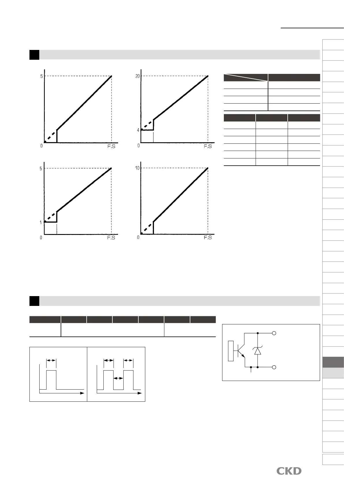
Analog output
(option code: blank, -A1, -A2, -A3)
1
●
The relation between the ow rate and the analog
output is as in the gure on the left. Note that the
analog output is not output normally at the min.
value or less. However, the ow rate display in the
monitor is displayed even at the min. value or less.
●
Never make a short circuit between the
analog output terminal (ANO) and
another terminal. This may lead to failure.
●
Make the cable short so as not to be affected
by noise and keep it away from all noise
sources such as power distribution wires.
●
When extending the cable,
Product name : Extension cable
Model No. : PF-FL-280775
Use (length of 3 m).
Use the cable with total length of 10 m or less.
2
Integrated pulse output
(option code: -A6)
●
For the integrated pulse output, a pulse is output per the integrated value below.
●
Electrical specication
◆
Output circuit
The integration display is updated at intervals of approx. 1 sec.
Descriptions
Analog output
Load resistance
0 to 5 VDC 50 kΩ or more
4 to 20 mADC 500 Ω or less
1 to 5 VDC 50 kΩ or more
0 to 10 VDC 50 kΩ or more
Analog output (V)
Analog output (V)
Analog output (V)
Analog output (mA)
Min. value
Min. value
Min. value
Min. value
Time
OFF
ON 25
msec
25 msec25 msec
Time
OFF
ON
25 msec
When the integration display is increased by 0.20 m³ (normal)
When the integration display is increased by 0.10 m³ (normal)
Internal circuit
Transistor
output
GND common
GND
PULSE OUT
Rating of transistor output
Max. rated voltage 30 VDC
Max. rated current 50 mA
0 to 5 VDC [blank] 4 to 20 mADC [-A1]
1 to 5 VDC [-A2] 0 to 10 VDC [-A3]
Flow rate L/min (normal)
Flow rate L/min (normal) Flow rate L/min (normal)
Flow rate L/min (normal)
F.R.L
F (Filtr)
R (Reg)
L (Lub)
PresSW
Shutoff
SlowStart
FlmResistFR
Oil-ProhR
MedPresFR
No Cu/
PTFE FRL
Outdrs FR
F.R.L
(Related)
CompFRL
LgFRL
PrecsR
VacF/R
Clean FR
ElecPneuR
AirBoost
SpdContr
Silncr
CheckV/
other
Jnt/tube
AirUnt
PrecsCompn
Mech/
ElecPresSw
ContactSW
AirSens
PresSW
Cool
AirFloSens/
Contr
WaterRtSens
TotAirSys
(Total Air)
TotAirSys
(Gamma)
RefrDry
DesicDry
HiPolymDry
MainFiltr
Dischrg
etc
Ending
1383
 Loading...