EasyManua.ls Logo

Clarion DRB4475R - User Manual

Clarion DRB4475R
17 pages
To Next Page IconTo Next Page
Loading...
Clarion
Malaysia
Sdn.
Bhd.
Phase
3,
F.7.Z..
Bayan
Lepas,
11900
Penang
Published
by
Clarion
Malaysia
4
Tel.:
(04)
6439106/7,
Fax:
(04)
6438763
Clarion
Co.
Ltd.
Export
Division
~
22-3,
Shibuya
2-chome,
Shibuyaku,
Tokyo,
150
Japan
5
mo
Tel:
(03)
34001121
Printed
in
Malaysia
Nov.
1997
AM/FM
CD
Player
with
CD
Changer
Control
voit
DRX5375R
(PE-2231E-B)
=”
AM/FM
CD
Player
e
vec
DRB4475R
(PE-2270
E-A/illumination:Amber)
(PE-2270
E-B/illumination:Green)
MSPECIFICATIONS
cial
HBS
&
Seg
FM
tuner
section
_
Ground:
Negative
ground...»
;,.,.
-
Frequency
range:
87.5
to
108MHz
(0.05MHz
steps)
Speaker
Impedance:
42(4Q.
to
8Q)
.
Current
consumption:
2
MW
tuner
section
i
Less
than
10A
|
o..
psiy
ex,
Frequency
range:
531
to
1602kHz
(9kHz
steps)
Dimensions:
178(W)x50(H)x155(D)mm,
....::
Weight:
V.7KQ
©
songs
adi
tagare
ce
LW
tuner
section
ee
eae
Frequency
range:
153
to
279kHz
(3kHz
steps)
BICOMPONENTS
©:
;
PE-2231E-B,
PE-2270E-A/E-B
CD
player
section
Main
unit
.
RET
G
1
System:
Compact
disc
audio
system
Parts
Bag
Usable
disc:
Compact
disc
Extension
lead
.
ae
850-668100
1
Frequency
response:
=
Hook
Plate
in
:
330-82160L-
2
;
_——__-TOHz
to
20kHz
(1B)
Lead
holder
(PE-2231E-B
Only)
335-083901
1
Signal
to
Noise
ratio:96dB
(1kHz,!HF-A)
Shrew
74
6-0726041
1
Dynamic
range:
95dB
(1kHz)
Spaser
i
gaa
345-36530
4
1
craven
casa
DCP
Case
_
835-533130
1
Mounting
bracket
boy
300-903503
1
General
.
>
Maximum
power
output:
we
30Wx4ch
%x
Specifications
comply
with
EIA
Standards.
Power
supply
voltage:
*
Specifications
and
the
design
are
subject)
change
14.4V
DC
(10.8V
to
15.6V)
without
notice
for
further
improvement.
Ae
DRX5375R/DR_475R
j
,
:
Ok
Question and Answer IconNeed help?

Do you have a question about the Clarion DRB4475R and is the answer not in the manual?

Clarion DRB4475R Specifications

General IconGeneral
TypeCD Receiver
Channels4
TunerFM/AM
Preamp Outputs2-channel
Aux InputYes
Signal-to-Noise Ratio90dB
CD CompatibilityCD-R/RW

Summary

SPECIFICATIONS

FM tuner section

Details the frequency range and steps for FM reception.

MW tuner section

Details the frequency range and steps for MW reception.

LW tuner section

Details the frequency range and steps for LW reception.

CD player section

Specifies system, usable disc, frequency response, and S/N ratio for CD playback.

General

Lists maximum power output and power supply voltage requirements.

COMPONENTS

Main unit

Lists main components like PE-2231E-B and PE-2270E-A/E-B models.

Parts Bag

Refers to the included parts bag for the main unit.

Accessory Parts

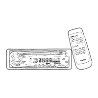
Lists specific accessory parts like extension lead, hook plate, and lead holder.

Fasteners and Brackets

Lists screws, spacers, DCP cases, and mounting brackets.

Repair and Inspection Precautions

Use Specified Parts

Emphasizes using only original or equivalent parts for safety and liability.

Proper Part Placement

Stresses correct placement of parts and wiring to avoid issues.

Post-Repair Safety Check

Highlights the importance of checking for secure parts and potential secondary problems.

Automotive Wiring Cautions

Warns about disconnecting battery and correct wiring to prevent short circuits and fires.

Chip Component Handling

Advises on reusing chips and handling tantalum capacitors carefully.

Flexible PWB Handling

Provides guidelines for soldering iron temperature and force on flexible PCBs.

Disassembly and Replacement Procedures

Instructs to turn off the unit and recheck work before powering on.

Optical Pickup Light Check

Advises keeping eyes more than 30cm away when checking optical pickup light.

Optical Pickup Handling Precautions

Details precautions for handling optical pickups, including static discharge and cleaning.

CAUTIONS

Class 1 Laser Product Warning

Identifies the appliance as a Class 1 Laser Product and advises reading the manual.

Vehicle Specific Notes

VW;Audi Fuse Installation

Instructs on changing fuse installation position for VW and Audi vehicles.

Cellular Mute Connection

Explains connecting the lead for the triggered audio mute function for cellular telephones.

ERROR DISPLAYS

CD Deck Errors

Lists error codes (CD ER2, CD ER3) and their causes/measures for the CD deck.

CD Changer Errors

Lists error codes (CDCH ER2, ER3, ER6) and their causes/measures for the CD changer.

TROUBLESHOOTING

Power and Sound Issues

Addresses problems like no power, no sound, noisy sound, and sound distortion.

Loading and Display Problems

Covers issues with CD loading, button response, display accuracy, and connector dirt.

ADJUSTMENTS

S-meter Adjustment

Provides a procedure for adjusting the S-meter reading using a signal and test mode.

IC Terminal Descriptions

µPD178016 GC-511-3 B9 IC Details

Provides the part number and form factor for the main microcomputer IC.

Terminal Functionality

Details the function of each terminal pin on the µPD178016GC IC.

Exploded View and Parts List

Main Section Diagram

Presents an exploded diagram of the main unit with numbered parts.

Block Diagram

SW PWB Section Diagram

Illustrates the functional connections within the SW PWB section.

Electrical Parts List

SW PWB Section Components

Lists electrical components for the SW PWB section with part numbers and descriptions.

Main PWB Section Parts

Component Listings

Provides a detailed list of parts for the Main PWB section.

CD Mechanism Section Parts

Component Listings

Lists electrical components for the CD Mechanism section with part numbers and descriptions.

Circuit Diagrams (1;3)

SW PWB Circuit Diagram

Shows the detailed circuit diagram for the SW PWB section.

Printed Wiring Board

SW PWB Layout

Displays the physical layout of the SW PWB with component placement.

Circuit Diagrams (2;3)

Main PWB Section Circuit Diagram (1;2)

Shows the first half of the detailed circuit diagram for the Main PWB section.

Circuit Diagrams (3;3)

CD Mechanism Section Circuit Diagram

Displays the detailed circuit diagram for the CD Mechanism section.

Printed Wiring Board

CD Mechanism PWB Layout

Shows the physical layout of the CD Mechanism PWB with component placement.

Exploded View

CD Mechanism Exploded View Parts

Presents an exploded diagram of the CD mechanism with numbered parts.

Circuit Diagram

CD Mechanism Circuit Diagram

Illustrates the detailed circuit diagram for the CD Mechanism section.

Printed Wiring Board

CD Mechanism PWB Layout

Shows the physical layout of the CD Mechanism PWB with component placement.

Exploded View

CD Mechanism Exploded View Parts

Presents an exploded diagram of the CD mechanism with numbered parts.

Related product manuals