- 19 -
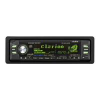
QX-3870N-A
1
ffix sheet XM (B) to XM-PWB (A).
A1
B2
2
ffix sheet HS-XM2 (D) to undercover (C).
C1
D1
ttach it aligned with the stamp on the undercover.
3
E4
Tightening torque: 0.4 N·m
Tightening sequence is specified. (1) to (4)
4 F 1 Insert the terminal surface facing up.
5
ffix sheet TUN (G) to the TUNER of the AUDIO-PWB part.
G 1 Attach it aligned to the TUNER unit.
6
Insert 3 undercover tabs and fit 6 dowels.
[Precautions for AUDIO-PWB handling]
* Do not subject the AUDIO-PWB FAN to strong impact. If it is dropped from a height of 20 cm or more, discard it.
* Do not touch the rotating part of the AUDIO-PWB FAN.
* Pay sufficient attention in handling so that the FAN inside the AUDIO PWB does not hit other parts.
(1)
Electric screwdriver (0.4±0.04 N·m)
Insert FFC-23PIN-80MM (F) between the XM-PWB connector
and the main unit assy AUDIO-PWB connector.
(Insert in the order of the main unit assy side then XM-PWB
side)
Install the undercover part on the main unit assy.
(Refer to Fig. 1.)
While pushing it into the front surface side of the
undercover, fit and install it on the main unit assy.
MJZ0532
Part No.
.8829012A
MQZ0091
Tools to be used
Important control items
Qty
Work processing drawing Work procedures
No.
Assembly 6
QX-3870N-A
(NAU-3225KCA-C)
07
Attach it to the board so that it does not ride on the
IC.
MQZ0084
QAZ2308
Be careful that the ☆ 2 tabs do not contact the
XM-PWB.
After inserting it into the main unit assy side,
perform wire termination of the FFC on the front
plate inside.
The undercover should not ride on the AUDIO-
PWB part.
Place the XM-PWB part on the undercover and tighten it with
2.6 x 8 screws (E).
EKZ0171
MQZ0103
A
B
(B)
C
D
F
(1)
(2)
(3)
(4)
(Fig. 1)
(C)
Do not attach
to this part.
Dowels
G
E
XM PWB side
AUDIO PWB side
Stamp
Dowels
Stamp
 Loading...