5
Posioning of the Components Microphone, Loudspeaker and Intercom Console
Loudspeaker
- Mounng on the ceiling above the user,
or on the wall below the ceiling behind the user
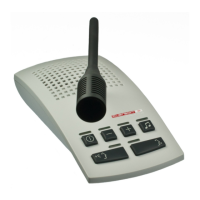
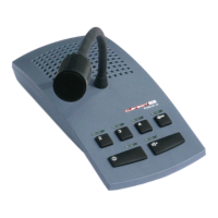
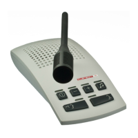
Intercom Console
- the intercom console has to be placed as far from the
control room door as possible
Maximum speech distance to the microphone: 10cm
Microphone
- ceiling xaon
- as close to the user´s working posion as possible
- avoid collision with other components suspended from the ceiling
4
U
2x C
H
N
Service and Installaon Instrucons
German
English
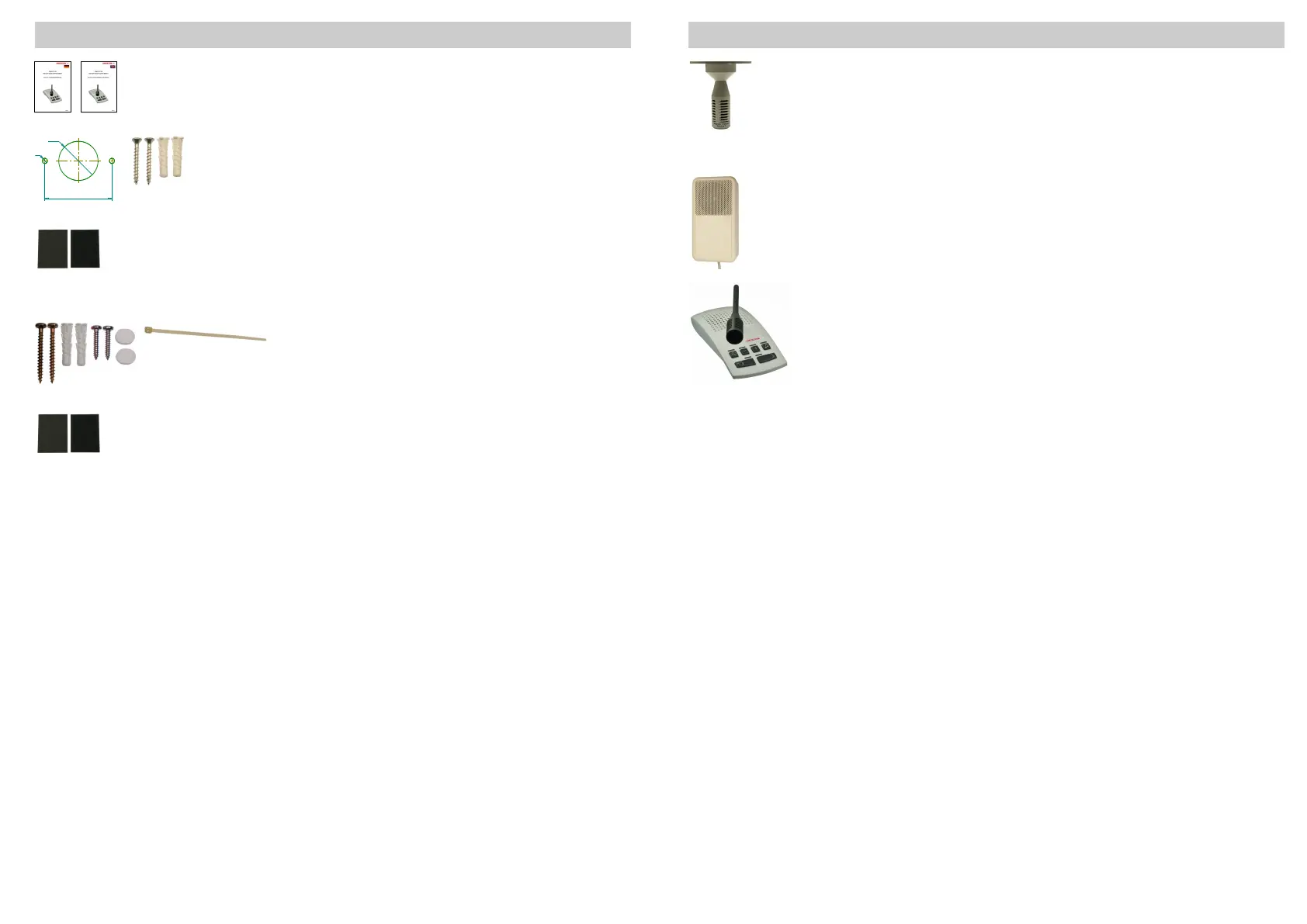
Mounng material for microphone ceiling xaon:
drilling template
2 counter-sunk head screws 3,5x30mm + 2 wall plugs
5x25mm
Mounng material for connecon hub
1 hook-and-loop fasteners
(4)
Mounng material for loudspeaker
4 screws 3,5x35mm, 4 wall plugs 5x25mm
2 screws 2,9x16mm, 2 decorave caps
cable es 100mm
Mounng material for power supply
hook-and-loop fastener
(4)
V
Delivery Contents Mounng Material
((4)
Use hook-and-loop fasteners only on suitable surfaces (adhesion)!
35.054.440.006
35.054.440.007
35.054.006
40.054.844
40.054.830.001
40.054.827
40.054.831
40.054.832
40.054.830.002