Electrical (continued)
10
Step 1: Mount the 4-20mA controller to a suitable vertical surface according to the installation manual supplied
with the controller.
Step 2: Wire the #22 AWG orange ‘positive’ (+) lead from the ozone generator to the 4-20mA controller according
to the manual supplied with the controller.
Step 3: Wire the #22 AWG purple ‘negative’ (-) lead from the ozone generator to the 4-20mA controller according
to the manual supplied with the controller.
Step 4: Complete the required programming and calibration steps as outlined in the installation manual supplied
with the 4-20mA controller.
Step 5: Air Preparation System Power: 120VAC systems only: plug the power cord into main power. 240VAC
systems only: the power cord must be hard wired to the main power source (Black-L1, White-L2/N and Green-Ground).
Notes: The prescribed air flow of the air prep system must be set to “atmospheric pressure” prior to use, follow
Step 5 of the ‘Start-up & Calibration' section. Warnings: Failure to calibrate may lead to premature failure of the
air preparation system. Vacuum from the venturi must be interrupted if the air prep system is not “ON;” failure
to do so will damage the air prep system.
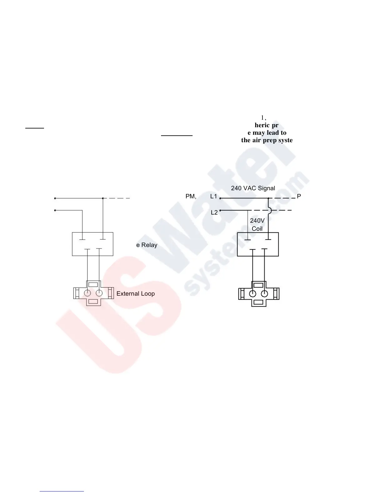
External Loop Electrical Interface
Figure 5-1