This section outlines the steps required to complete the
ozone system pneumatic hook-ups. The system
components include the air preparation system, ozone
generator, vacuum break, and ozone injector manifold
(see Figure 6-1). The air preparation system provides the
ozone generator with a source of dry, oil-free oxygen-
enriched air (90% +/- 3% oxygen purity at -100˚F dew
point). The air is drawn from the ozone generator (where
ozone is produced from the oxygen in the air stream) and
through the vacuum break by the suction created at the
ozone injector manifold.
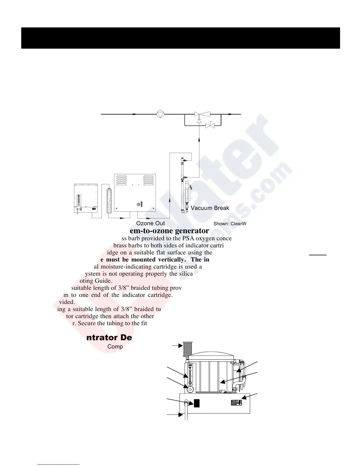
Figure 6-1
Hook-Up: Air preparation system-to-ozone generator
Step 1: Teflon® tape and attach brass barb provided to the PSA oxygen concentrator outlet.
Step 2: Teflon® tape and attach brass barbs to both sides of indicator cartridge (ordered separately).
Step 3: Mount indicator cartridge on a suitable flat surface using the Clic® mounting clamps provided. Notes: The
indicator cartridge must be mounted vertically. The indicator cartridge does not have a direction of
flow. An external moisture-indicating cartridge is used as a reference to indicate the quality of the dry air, if
the air prep system is not operating properly the silica will turn from blue and white in color to all white. See
Troubleshooting Guide.
Step 4: Using a suitable length of 3/8” braided tubing provided, attach one end of the tubing to the oxygen concentrator
system to one end of the indicator cartridge. Secure the tubing to the brass fittings with the hose clamps
provided.
Step 5: Using a suitable length of 3/8” braided tubing, attach tubing to the brass barb located at the other end of the
indicator cartridge then attach the other end of the tubing to the brass barb located at the bottom of the ozone
generator. Secure the tubing to the fittings with the hose clamps provided.
Oxygen Concentrator Detail
Figure 6-2