Vitec Group Communications
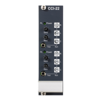
CCI-22 Dual Channel Party-Line Interface Instruction Manual
2-2
located near the center of the CCI-22 main circuit board, and are
shown as a detail in the assembly drawing for the CCI-22 main circuit
board in the Maintenance Chapter. When either jumper is next to the
label “B”, its termination is disabled; moving the jumper next to the
label “A” enables the termination.
WIRING
The CCI-22 interfaces are connected to the matrix frame through the
two RJ-45 connectors on the IMF-3 or IMF-102 rear-panel assembly
(part no. 710538Z) to which CCI-22 is connected. For connection to a
matrix frame refer to the “Installation in Interface Frame” on page 2-1.
For internal jumper settings and adjustments refer to “Adjustments” on
page 2-10.
The “user” side of the CCI-22 for each channel is on a pair of DB-9M
connectors on the rear of the interface frame. Figure 2-1 shows the
pinout of either one of these connectors. Both DB-9Ms are paralleled
such that both party-line channels are available on each connector. It
is possible to wire one DB-9 connector as channel #1, the second
DB-9M as channel #2, or bring both channels out either DB connector
separately or create a TW type party-line connection.
Figure 2-1: Pinout of the DB-9M Interface I/O Connectors
CLEAR-COM PARTY LINES GENERAL DISCUSSION
Stations on Clear-Com party-lines are connected with two-conductor
shielded microphone cable. One conductor carries the DC power (28
to 30 V), while the other carries the duplex two-way intercom audio
signal and DC “Call Light” signaling. The shield acts as common
ground for both the power and signal.
Power to the CCI-22 interface channels must be provided by the
external party-line. The power connection for each channel is the “+30
VDC Power” pin on the appropriate DB-9M Interface I/O connector
located on the rear-panel assembly. The CCI-22 channel is essentially
just another “beltpack” on the party-line.
6
7
8
9
1
2
3
4
5
Channel 2 Channel 1
CC/RTS
Ground
+30 VDC Power
Audio
CC/RTS
Ground
+30 VDC Powe
Audio
Chassis Ground