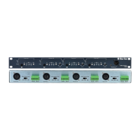
IF4W4 4-CHANNEL FOUR-WIRE INTERFACE
2-1
INSTALLATION
Installation and setup requirements are the same for all channels of the IF4W4
interface (i.e. A, B, C, or D channels). The following describes installation of a
four-channel interface.
The IF4W4 interface can be set up to operate as four independent interfaces, or
may be internally bussed into a single common party line. Therefore installation
requirements will vary according to the configuration. Installation for four-wire
and headset emulation are discussed separately.
PARTY LINE INSTALLATION
To connect Clear-Com to the interface, route a two-conductor shielded cable
from a Clear-Com main or remote station output connector to the IF4W4 rear
panel. Connect the cable to the XLR connector input marked Channel A, B, C
or D. The pin assignments in a Clear-Com 3-pin intercom connector are:
Pin 1--- Common
Pin 2 --- Power
Pin 3 --- Intercom audio
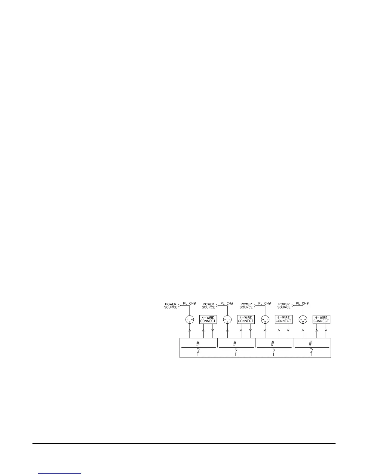
CONNECTION TO PARTY LINE: INDEPENDENT INTERFACES
In a multi-channel configuration, each channel of the IF4W4 is individually
powered from the party-line source (Clear-Com). Connect a Clear-Com line to
each of the channels and set link switches to OFF.
The figure below illustrates the connections for this type of installation.
Figure 2-3: Typical Multi-channel Use
FOUR-WIRE IN/OUT
To connect a four-wire device to the interface, for each channel, attach one set of
four-wire output lines to one set of terminal block connectors on the IF4W4 rear
panel. On the terminal block, pins #1 and #2 are for input (Receive) and pins #4
and #5 are for output (Transmi t). Pin #3 is unit ground.
A
B
CD
AB CD
IF4W4
4-CHANNEL FOUR-WIRE
INTERFACE
2