7
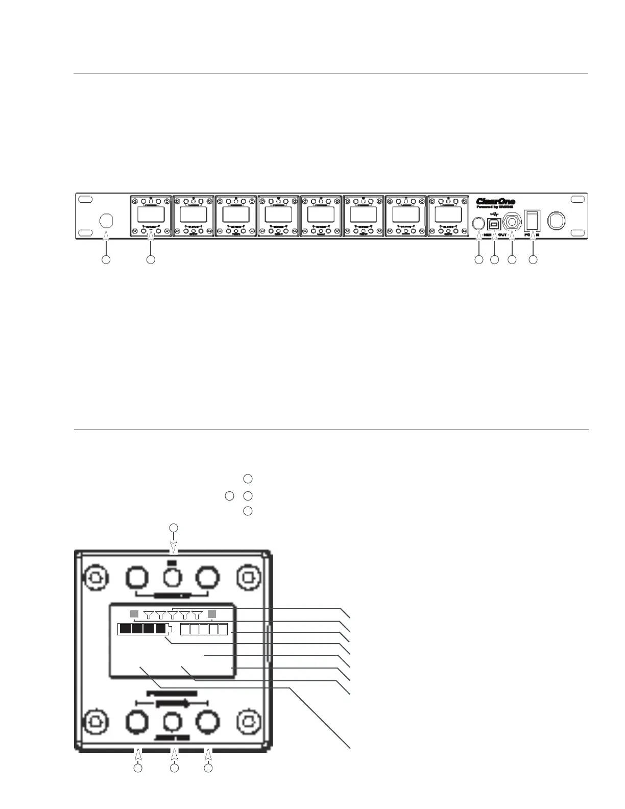
Receiver Module:
1. Antenna Front Mounting Hole: Use back-to-front TNC cables included.
2. Receiver Module (See details below).
3. Mixed audio volume control.
4. USB Port. Connect to computer for ClearOne Remote control. Run software to monitor/edit system
parameters, scan for RF interference and download firmware upgrades.
5. Mixed audio output, 1/4” phone jack for monitoring individual channels or mixed channels.
Note: Factory default for the front panel headphone jack is set for mixed line-level out.
Use ClearOne Remote>Settings>Headphone, to reset for headphones.
6. Power Switch.
ClearOne receiver main-frames hold either four or eight, independent, 24-bit digital audio receiver modules.
There is a front-panel mixed audio output for headphones or direct recording. Each module shares the main-
frame’s two antennas for full-diversity. Receiver main-frames can be daisy-chained together allowing up to
32 channels in an antenna network that shares two antennas. This eliminates the need for external antenna
distribution amps. Main-frames can be connected to form an Ethernet network that monitor and control the
system via a computer. Main-frames also have USB and RS232 connections for serial monitor and control.
IR Sync LED: Sends IR information to SYNC the receiver and transmitter (SYNC pg. 5).
Pressed at the same time: Sends SYNC signal from receiver to transmitter (SYNC pg. 5).
Status LED:
• Green --> The channel is ON and un-muted
• Red --> The channel is OFF
• Flashing Red --> Encryption key mismatch or, two transmitters are synced
to the same Receiver. Solution: Re-sync receiver with transmitter.
• Amber --> The receiver is muted or GPIO is triggered
Modules are designed for quick and easy field replacement for added redundancy.
FRONT PANEL:
BATTERY
AUDIO
SLOT 3
CH 1
ON
AES256
RF BARS
AUDIO LEVEL
BATTERY LEVEL
CHANNEL NAME
ENCRYPTION
STATUS:
ON = Green
OFF = Red
MUTE = Amber
KEY = Flashing Red (“KEY” = mismatched encryption key)
MODULE:
FREQUENCY
1
2
ANTENNA DIVERSITY
(Colored text indicates status)
1
2
3 4
5 6
1
2
3
4
Receiver:
1
2
&
4
3