BNP
®
55 SUCTION BLAST CABINET Page 24
© 2019 CLEMCO INDUSTRIES CORP. www.clemcoindustries.com Manual No. 23350, Rev G, 02/19
7.9.20 (6th) Use self-drilling screws through the
existing holes to secure the side-inlet liner to the side of
the inlet housing. NOTE: To field install new, first-time
inlet-side liners, use self-drilling screws at each liner
corner to secure. Remove the clamps after the liner is
secured.
7.9.21 (7th) Align the front edge of the inlet-top liner to
the front of the inlet housing and use self-drilling screws
through the existing holes to secure. NOTE: To field
install new, first-time inlet-top liners, after clamping the
liners, use self-drilling screws at each liner corner to
secure. Remove the clamps after the liner is secured.
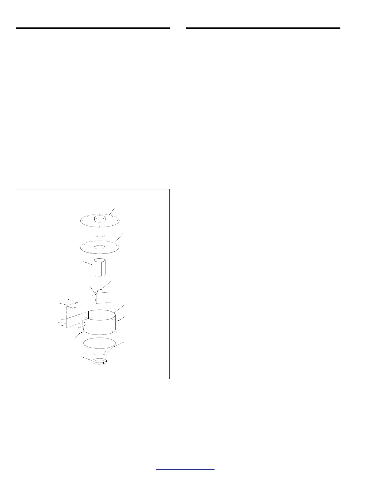
7.9.22 (8th) Slide the top liner onto the inner tube and
align the holes in the liner with those in the top. Note that
the holes around the inlet are spaced differently from the
others. Temporarily install a couple of bolts to keep it in
alignment.
Figure 27
7.9.23 (9th) Place the cylinder liner over the inner tube.
Make sure the liner is tight against the top liner and use
worm clamps to temporarily clamp the liner to the tube.
Tack weld the bottom of the cylinder liner to the inner
tube in three or four places. Remove the clamps when
the cylinder liner is secured.
7.9.24 Apply caulking to the seam on the cylinder liner
and between the cylinder liner and top liner.
7.9.25 Apply caulking around the top edge of the wall
liner and top-inner edge on the inlet housing.
7.9.26 (10
th
) Align the reclaimer top assembly over the
top of the reclaimer and lower it into place to match the
mating holes in the flange, being careful not to smear
the caulking. Secure the top bolts and inlet baffle bolts.
7.9.27 Working through the reclaimer inlet, wipe the
caulking seal smooth. Re-caulk any voids.
7.9.28 Working through the reclaimer inlet, apply
silicone caulking to seal seams around the inlet-side
liner, inlet-top liner, and reclaimer weldment. Wipe the
caulking smooth.
7.9.29 Attach the inlet-pipe adaptor, replacing the
gasket if worn, compressed, or otherwise damaged.
7.9.30 Reattach the reclaimer to the cabinet.
7.9.31 If the lower flange gasket (usually installed on
the hopper flange) is worn, compressed, or otherwise
damaged, clean old gasket material from the flange and
install new 2" strip gasket and attach the hopper.
7.9.32 Install flex hoses.
7.9.33 Allow time for the caulking to cure before putting
the reclaimer in service
7.10 Replacing or Removing Reclaimer Inlet
Baffle ‒ Figure 28
600 cfm reclaimers only with bolt-on tops.
When using lightweight media such as agricultural
media or very fine media (180 and finer), as noted in
Paragraph 1.9.6, good media may be carried over to the
dust collector. To prevent lightweight-media carry over,
the inlet baffle of the reclaimer can be removed. Review
the following process before beginning to make sure all
parts are available:
Installation Notes:
Make sure enough 13089 - 2" adhesive-backed gasket
is available to replace compressed or damaged gaskets
on the reclaimer upper flange (and lower hopper flange
if the hopper is removed from the reclaimer).
300 cfm none required. Baffle is not removable.
600 cfm requires 6 ft for each flange.
Reclaimer Top and
Inner Tube (10
th
)
Top Liner (8
th
)
Cylinder Liner (9
th
)
Inlet-Top Liner
th
Lined Baffle (5
th
)
Bolts enter from inside.
Baffle Bolts and
Flat Washers
Inlet-Side Liner
3rd
and
6
th
Wall Liner (4
th
)
Self-Drill/Tap
Screws
Baffle Lock Washers
and Nuts
Cone Liner (2
nd
)
Cone-Ring Liner (1
st
)