Model: 22, 32
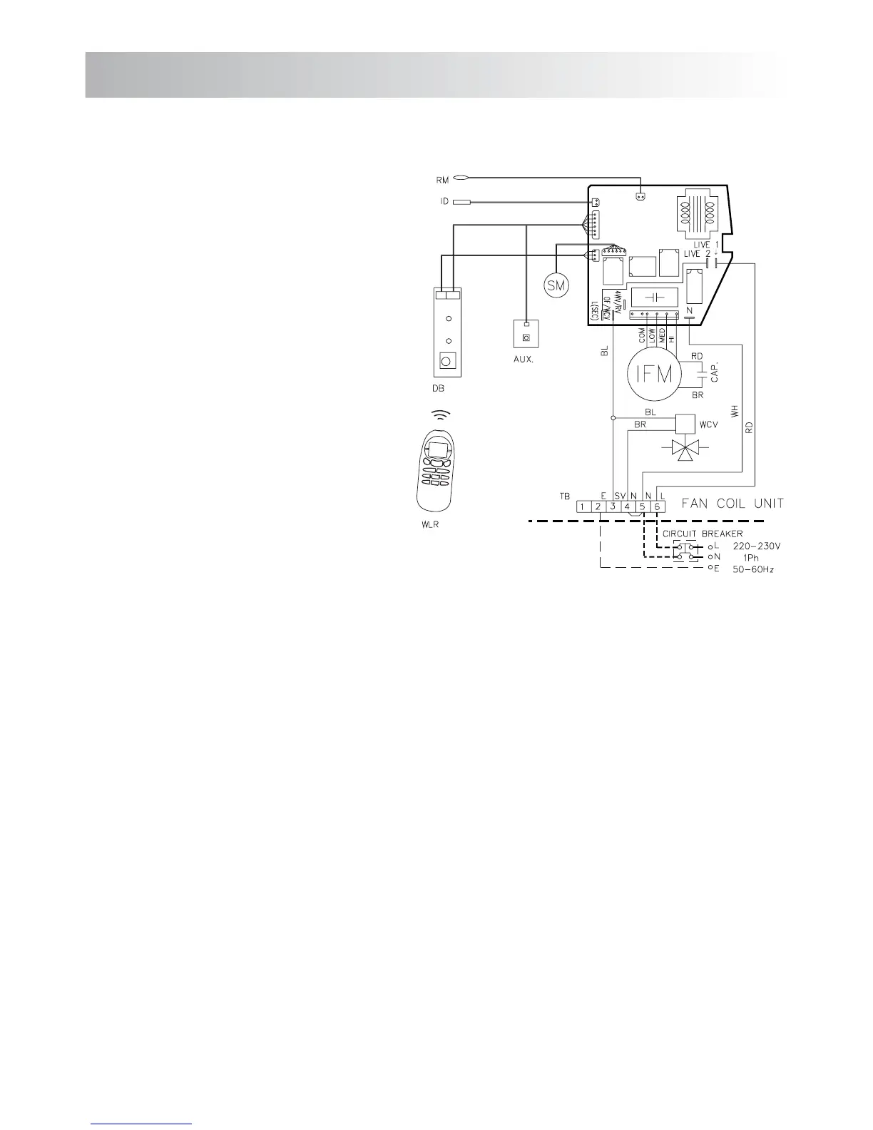
LEGENDA / LEGEND:
AUX: Przełącznik pomocniczy / Auxiliary switch
DB: Odbiornik sygnału pilota / Display board
ID: Czujnik temperatury wymiennika / Indoor coil thermistor
IFM: Silnik wentylatora jedn. wewn. / Indoor fan motor
RM: Czujnik temp. w pomieszczeniu / Room sensor
SM: Silnik krokowy / Step motor
TB: Listwa zaciskowa / Terminal block
WCV: Zawór regulacyjny wody / Water control valve
WIR: Pilot przewodowy (opcjonalny) /
Wired remote unit (optional)
WLR: Pilot bezprzewodowy / Wireless remote unit
LEGENDA DO LISTWY ZACISKOWEJ
TERMINAL BLOCK LEGEND
6: Faza / Live connection
5: Zero / Neutral connection
4: Zero / Neutral connection
3: Zawór regulacyjny 3-drogowy /
Water control valve connection
2: Uziemienie / Earth connection
KOLORY PRZEWODÓW / WIRE COLOURS
BK: Czarny / Black
BL: Niebieski / Blue
BR: Brązowy / Brown
GR: Zielony / Green
RD: Czerwony / Red
WH: Biały / White
YL: Żółty / Yellow
UWAGI / NOTES:
1: Linią przerywaną oznaczono okablowanie do wyko-
nania na miejscu montażu.
Wiring dotted to be fitted by installer
2: Jednostkę należy zamontować zgodnie z lokalnymi
przepisami dotyczącymi instalacji elektrycznej.
The unit shall be installed according to national wiring
regulation.
3: Połączenie silnika wentylatora jednostki wew-
nętrznej; modele 22-32
Regulacja obrotów wentylatora: wysokie (BK), śred-
nie (GR), niskie (YL).
Indoor fan motor connection; models 22-32
Indoor fan speed connection; high (BK), mediom
(GR), low (YL).
12
10. SCHEMATY ELEKTRYCZNE
10. WIRING DIAGRAMS