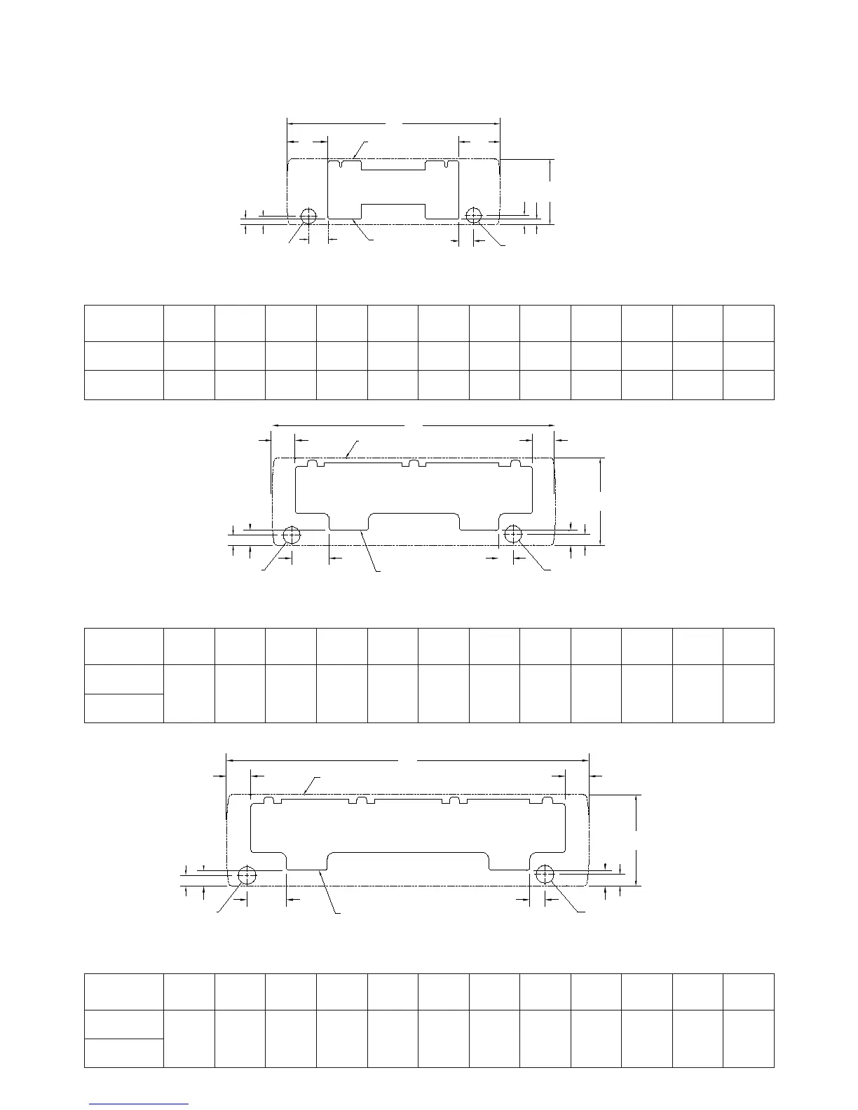
WYMIARY MONTAŻOWE STELAŻU POD JEDNOSTKĘ PLAN DIMENSIONS FOR MOUNTING PLATE
INSTALLATION
MODEL
A B C D E F G H I J K L
22 880 298 190 190 90 68 42 20 26 20 Ø70 Ø70
32 990 305 191 191 91 69 39 27 43 27 Ø70 Ø70
MODEL
A B C D E F G H I J K L
42
1170 360 96 96 155 60 62 42 6262 46 Ø70 Ø70
53
MODEL
A B C D E F G H I J K L
72
1451 365 100 100 155 70 38 42 38 46 Ø70 Ø70
83
K
E
C
F
D
Zarys klimakonwektora
Outline of fan coil unit
Stelaż
Mouting plate
L
I J
B
H G
A
K
E
C
F
A
Zarys klimakonwektora
Outline of fan coil unit
Stelaż
Mouting plate
L
I J
B
H G
D
Wymiary w milimetrach
Dim. are in millimeter
Wymiary w milimetrach
Dim. are in millimeter
Wymiary w milimetrach
Dim. are in millimeter
K
E
C
F
A
Zarys klimakonwektora
Outline of fan coil unit
L
I J
B
H G
Otwór pod rury prowadzone
do tyłu w lewo
Left backward piping hole
Otwór pod rury prowadzone
do tyłu w prawo
Right backward piping hole
Otwór pod rury prowadzone
do tyłu w lewo
Left backward piping hole
Otwór pod rury prowadzone
do tyłu w prawo
Right backward piping hole
Otwór pod rury prowadzone
do tyłu w lewo
Left backward piping hole
Otwór pod rury prowadzone
do tyłu w prawo
Right backward piping hole
D
Stelaż
Mouting plate
6