14
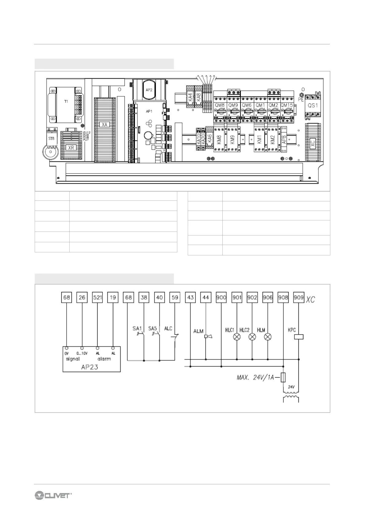
6.6 ELECTRICAL PANEL
AP1 Master module
AP2
Electronic thermostatic module
XC Customer connection
QS1 Main isolator switch
QM1 - QM2 Compressor magnetothermic switch
KM1 - 2 Compressor contactor
6 - ELECTRICAL CONNECTIONS
QM8 - QM9
Electric heart thermal magnetic circuit breakers
KM8 - KM9 Heater contacotr
QM6 Outlet fan motor overload switch
QM15
Auxiliary circuit thermal magnetic circuit
breaker
ST8 High temperature saftey thermostat
T1
Auxiliary circuit transformer
6.7 CONNECTIONS
SA1 remote on/off selector
SA5 remote winter/summer selector
ALC free contact from signalling system of fire alarm
ALM cumulative fault signal
KPC heating coil pump control
HLC1 compressor 1 status
HLC2 compressor 2 status
HLM indicating light of the supplì fan status
AP23 remote umidification group
Layout of the standard unit electrical panel.
With special configurations the layout can be modified: refer to the layout indicated on the unit specific electrical panel.

 Loading...