15
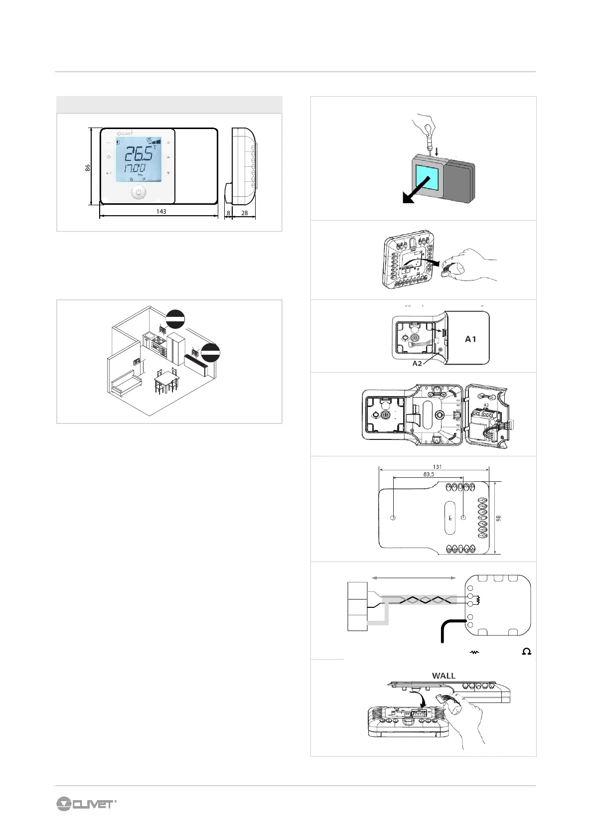
Install the room thermostat far from heat sources (radiators,
sunbeam, kitchens), from doors , windows etc.
Provide 230 VAC power supply
6.8 WALL AMBIENT THERMOSTAT
1,5 m
OK
6 - ELECTRICAL CONNECTIONS
ASSEMBLY
• separate the front from the rear of the terminal using a
screwdriver (Fig. 1);
• disconnect the 4-pin connector from the front part (Fig. 2);
• to remove cover A1, unscrew screw A2 and press the
point of attachment (Fig. 3); access terminal block A3
(Fig. 4)
• drill the holes in the wall (dia. 5 mm); then insert the plugs
and screws supplied, making sure that the electrical wires
pass through hole E (Fig. 5);
• perform the electrical connections between thermostat
ambient and XC terminal block in the unit electric panel
(Fig 6)
Connect RT2 (provided with room thermostat)
•
close cover A1, completing the same operations as
descrive above in reverse;
• plug the 4-pin connector back in (Fig. 8);
• fi nally replace the terminal, starting with the bottom tabs
and applying a hinge movement. Make sure that the
electrical wires are inside to ensure correct fastening (click
on).
DISMANTLING
Insert a screwdriver into the clot at the top (Fig. 1) and press
downwards to detach the display.
1
2
3
4
6
5
7
GND
F+
F-
xc
230 VAC
MAX 200mt
= RT2 = 120
Rx+ / Tx+
Rx- / Tx-
GND
N 230V~
L 50/60Hz

 Loading...