18
Installation
2.4.6 Electrical connections
Cables with the following characteristics are required to
power the outdoor unit:
Outdoor
unit
Mains power supply
V/Hz/p no.of cables/cross section
35M 230 / 50 / 1
2 x 2.5mm
2
+ G
53M 230 / 50 / 1
2 x 2.5mm
2
+ G
70M 230 / 50 / 1
2 x 2.5mm
2
+ G
88M 230 / 50 / 1
2 x 2.5mm
2
+ G
105M 230 / 50 / 1
2 x 4mm
2
+ G
105T 230 / 50 / 1 2 x 4mm
2
+ G
120M 400 / 50 / 3 + N
4 x 2.5mm
2
+ G
140T 400 / 50 / 3 + N
4 x 2.5mm
2
+ G
160T 400 / 50 / 3 + N
4 x 2.5mm
2
+ G
The indicated cross-sections are suitable for a wiring
length of up to 5 metres.
Cables with the following characteristics are required for
power supply and communication between the indoor
and outdoor units:
Indoor
unit
Power supply
to indoor unit
Signal
to indoor unit
no.of cables/
cross section
no.of cables/cross section
35M
2 x 1mm
2
+ G
2 x 1mm
2
53M
2 x 1mm
2
+ G
1 x 1mm
2
70M
2 x 1mm
2
+ G
2 x 0.2mm
2
88M
2 x 1mm
2
+ G
2 x 0.2mm
2
105M
2 x 1mm
2
+ G
2 x 0.2mm
2
105T
2 x 1mm
2
+ G
2 x 0.2mm
2
120M
2 x 1mm
2
+ G
2 x 0.2mm
2
140T
2 x 1mm
2
+ G
2 x 0.2mm
2
160T
2 x 1mm
2
+ G
2 x 0.2mm
2
The indicated cross-sections are suitable for a wiring
length of up to 5 metres.
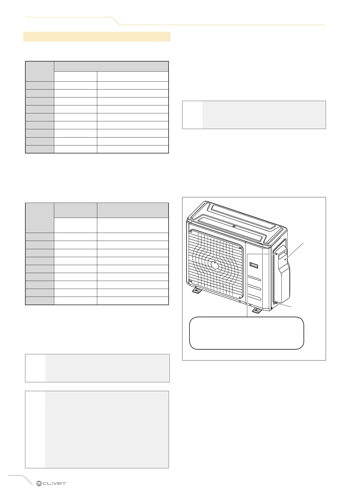
The terminal block of the outdoor unit is protected by a
cover on the side of the unit. A complete wiring diagram
is printed inside the cover.
f
ATTENTION ELECTRIC DANGER
Before making electrical connections, turn off
the main switch of the system.
l
WARNING
WRITE DOWN THE SPECIFICATIONS OF THE
FUSES.
The air conditioner board (PCB) is equipped with a
fuse for overcurrent protection. Fuse specifications
are printed on the circuit board, for example:
Outdoor unit:
T20A/250 Vac (for <24000Btu/h units),
T30A/250 Vac (for >24000Btu/h units).
NOTE: The fuse is ceramic.
1 Prepare the cable for connection:
– Using a wire stripper, strip the rubber sheath at
both ends of the cable and expose approximately
40 mm of the internal conductors.
– Strip the insulation sheath at the ends of the
conductors.
– Using a crimping tool, crimp U-type wire terminals
to the ends of the conductors.
m
CAUTION
When crimping, clearly identify live cables (“L”)
and other cables.
2 Unscrew and remove the terminal block cover.
3 Unscrew the cable clamp under the terminal block
and hold it aside.
4 Match the colours/labels of the cables to the labels
on the terminal block, then screw the U-shaped wire
terminal of each cable firmly to the corresponding
terminal block.
The wiring diagram of the outdoor unit is
located inside the terminal block cover.
Cover
Screw
Fig. 18
5 Check that all connections are stable, then wrap
the cables to prevent rainwater from entering the
terminals.
6 Attach the cable to the unit using the cable clamp.
Screw the cable clamp on firmly.
7 Insulate unused cables with PVC insulation tape.
Arrange them so that they do not touch electrical or
metal parts.
8 Replace the cover on the side of the unit and screw
it back on.
 Loading...