Do you have a question about the CLIVET MC2-Y Series and is the answer not in the manual?
Outdoor unit wiring diagram for the 35M series.
Outdoor unit wiring diagram for the 53M series.
Outdoor unit wiring diagram for the 70M series.
Outdoor unit wiring diagram for the 88M series.
Outdoor unit wiring diagram for the 105M series.
Outdoor unit wiring diagram for the 120M series.
Outdoor unit wiring diagram for the 105T series.
Outdoor unit wiring diagrams for 140T and 160T series.
EU Declaration of Conformity for the machine.
Crucial safety guidelines and precautions for operation.
Specific warnings about potential hazards and risks.
Actions that must not be performed to ensure safety.
Information on handling fluorinated gases.
Warning about flammable refrigerant use.
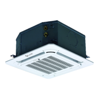
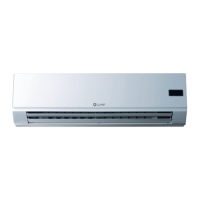
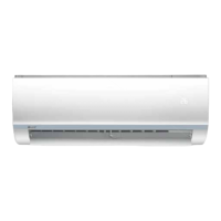
Identification of components in a 1:1 system.
Identification of components in a TWIN system.
List and description of included accessories.
How to identify the unit via serial number.
Procedures for receiving and checking the product.
Technical specifications for unit dimensions and weight.
Essential warnings before starting installation.
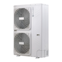
Detailed instructions for installing the outdoor unit.
Guidelines for selecting the appropriate installation location.
Safety note regarding drilling operations.
Warning about wall strength for wall-mounted units.
Tips for reducing vibration and noise from wall units.
Guidelines for installing multiple units in series.
How to configure TWIN indoor units with an outdoor unit.
Requirements for refrigerant pipe length and level difference.
Specifications for indoor unit connection pipe diameters.
Specifications for outdoor unit connection pipe diameters.
Setting the main-slave switches for indoor units.
Electrical connection for TWIN indoor and outdoor units.
Installation guidelines for oil traps in refrigerant piping.
Procedures for making electrical connections.
EMC regulations and magnetic ring usage.
Safety precautions for electrical connections.
Wiring diagrams for connecting indoor and outdoor units.
Wiring diagrams for 70M-120M models.
Wiring diagrams for 105T-160T models.
Steps for evacuating air from the refrigerant circuit.
Details on refrigerant pre-charge and additional charge.
Checks for electrical safety and gas leaks.
Procedures for checking electrical safety.
Methods for detecting refrigerant leaks.
Procedures for conducting operating tests.
Initial checks before performing the operating test.
Step-by-step guide for operating tests.
Steps to diagnose and resolve common issues.
Table of common anomalies and their solutions.
Possible causes and remedies for frequent starting/stopping.
Issues and solutions for poor heating performance.
Interpreting flashing indicator lights and error codes.
Meaning of LED error messages for outdoor units.
List of outdoor unit error codes and their descriptions.
Safety procedures for operating with R32 refrigerant.
Precautions for repairing sealed refrigerant components.
Guidelines for repairing intrinsically safe components.
Checks related to wiring integrity and influences.
Prohibited methods for detecting refrigerant leaks.
Acceptable methods for detecting refrigerant leaks.
Procedures for removing and evacuating refrigerant.
Guidelines for refrigerant charging procedures.
Procedures for unit disposal and component recovery.
General guidance on connecting refrigerant pipes.
Instructions for correctly cutting refrigerant pipes.
Process for removing burrs from cut pipe ends.
Steps for correctly flaring pipe ends.
How to connect refrigerant pipes without damage.
Detailed steps for connecting pipes to the indoor unit.
Detailed steps for connecting pipes to the outdoor unit.
Technical specifications for refrigerant piping.
Technical specifications for electrical connections.
| Refrigerant | R410A |
|---|---|
| Compressor | Scroll |
| Operating Range | Cooling: -15°C to 46°C |
| Power Supply | 400V/3Ph/50Hz |
| Control System | Digital |
| Dimensions | Varies by model, refer to specific model datasheet |
| Weight | Varies by model, refer to specific model datasheet |