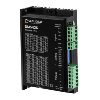
The Cloudray DM542S is a digital stepper drive designed to enhance the performance of stepper motors, offering advanced control and operational features. It is built on a new 32-bit DSP platform developed by TI, incorporating micro-stepping technology and a PID current control algorithm. This design aims to provide a superior experience compared to common analog stepper drives.
Function Description:
The primary function of the DM542S is to control stepper motors by converting input power into a PWM chopping wave, thereby regulating the voltage output to the motor. It supports various pulse input modes, including direction and pulse, CW/CCW double pulse, and A/B quadrature pulse input, making it versatile for different control systems. The drive is equipped with a 2MHz digital signal filter to ensure clean and reliable signal processing.
A key feature is its ability to automatically detect motor parameters during initialization, which helps optimize controlling performance. It also includes resonance suppression, automatically calculating resonance points and inhibiting IF vibration to ensure smooth operation. The DM542S can be enabled or disabled via a dedicated ENA port. When enabled, it outputs current to the motor; when disabled, it cuts off current to the motor phases, allowing the motor to move freely and not responding to step pulses. This ENA input can also be used to restart the drive after an error state, provided the fault has been cleared.
The drive's current control is based on a PID algorithm, which ensures precise and stable current delivery to the motor windings. It supports a wide range of micro-stepping settings, configurable via DIP switches, offering 16 different options to fine-tune motor resolution and smoothness. The running current can also be selected through DIP switches, with 8 different current selections available.
For power management, the DM542S can accept both AC and DC power, with an input voltage range of 24V to 50VDC. It's crucial to ensure the input power polarity is correct to prevent damage. The drive's constant current control mode means that the input power directly influences its performance.
Usage Features:
The DM542S is designed for ease of use and adaptability in various industrial applications. Its DIP switch configuration allows users to quickly set the desired running current and micro-stepping resolution without complex software. This flexibility makes it suitable for applications requiring different levels of precision and speed.
The drive is compatible with common 2-phase stepper motors with 4, 6, or 8 leads. For 4-lead motors, there is a single connection mode. For 8-lead motors, both series and parallel connection modes are supported. Series connection increases winding inductance, making it suitable for low-speed applications, with a recommended drive current setting of approximately 0.7 times the previous value. Parallel connection decreases winding inductance, ideal for high-speed requirements, with a recommended drive current setting of approximately 1.4 times the previous value. For 6-lead motors, parallel and central tapping connection modes are available. Parallel connection (all windings connected) results in higher inductance, suitable for low speeds, while central tapping (half windings connected) results in lower inductance, suitable for high speeds.
An important operational feature is the automatic current halving when the motor stops running (idle current). This function, configurable via DIP switch SW4, helps reduce motor and driver heating, thereby improving reliability. Users can choose between "half-flow" (current halved) or "full-flow" (current maintained) options. Generally, setting SW4 to "off" for half-flow is recommended to minimize heat generation.
The drive's input and output control signals are optically isolated, providing protection against electrical noise and ensuring robust communication with the upper controller, such as PLCs, MCUs, or control cards. The pulse level compatibility ranges from 3.3V to 24V, eliminating the need for external resistors.
The DM542S also features overvoltage, undervoltage, and overcurrent protection, safeguarding both the drive and the motor from potential damage due to abnormal electrical conditions. An LED indicator provides clear visual feedback on the drive's working status, including normal operation, various error states (overcurrent, overvoltage, internal voltage error, tracking error), and whether the drive is enabled or not.
Maintenance Features:
The DM542S is designed for straightforward installation and maintenance. It can be installed vertically or horizontally, with the front facing forward or top facing upward, respectively, to facilitate proper cooling. During assembly, it's important to prevent foreign matter from falling into the drive and to use M3 screws for secure fixing.
To ensure optimal performance and longevity, environmental requirements specify avoiding dust, oil, and corrosive environments. The operating temperature range is 0°C to 45°C with less than 90% RH (non-condensing), and storage/transportation temperature is -10°C to 70°C. Natural cooling is typically sufficient, but for multiple drives in a control cabinet, reserving enough space for heat dissipation or configuring cooling fans is recommended. The drive has an IP54 waterproof grade, offering protection against dust and splashing water.
In situations where there's a vibration source near the installation position, using a vibrating absorber or a vibration-resistant rubber gasket is advised to protect the drive.
The manual provides a comprehensive troubleshooting guide to address common faults. This includes solutions for issues like the power indicator being off, the motor not working (e.g., locked rotor, slow speed, drive protected, enable signal problem, incorrect command pulse), incorrect motor steering, and alarm indicators signaling various errors (e.g., motor cable disconnected, wrong motor connection, voltage too high/low, signal disturbed). It also covers problems related to incorrect position or speed (e.g., incorrect command input, wrong pulse per revolution setting, abnormal encoder signal) and drive terminal short circuits.
For instance, if the power indicator is off, checking the power supply circuit is recommended. If the motor rotor is locked but the motor doesn't work, increasing the signal current to 7-16mA is suggested. If the speed is too slow, selecting the right micro-stepping is the solution. For issues with motor steering, adjusting DIP SW5 or checking motor cable connections are provided as remedies. If the drive is protected, solving the alarm and re-powering is necessary.
The DM542S also includes a guarantee clause, offering a 12-month warranty period and free maintenance service from the date of delivery. However, this warranty excludes issues arising from improper connection (e.g., reversed power supply polarity, hot-plugging motor connections), operation beyond electrical and environmental requirements, or unauthorized internal device modifications. The maintenance process involves contacting customer service for rework permission and attaching a written document describing the drive failure phenomenon, along with contact and mailing information.