Do you have a question about the Cloudray DM422S and is the answer not in the manual?
Details the environmental conditions required for the proper functioning of the drive, including dust, oil, and corrosive environment.
Provides the physical dimensions of the drive unit, crucial for mounting and space planning.
Outlines specific guidelines for mounting the drive, including orientation and screw usage.
Details the function and grade of each port on the drive, including power and motor connections.
Explains the requirements and considerations for the power supply input, including voltage range and polarity.
Illustrates different methods for connecting stepper motors (4, 6, 8 wires) to the drive.
Describes how to connect control signals like PUL, DIR, and ENA for motor operation.
Details how to set the motor's running current using DIP switches SW1, SW2, and SW3.
Explains the use of DIP switches SW5-SW8 to configure micro-stepping resolution.
Describes the function of DIP switch SW4 for setting quiescent current mode (half/full flow).
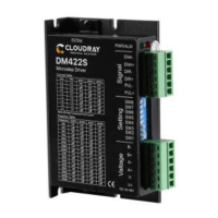
The Cloudray DM422S is a digital stepper drive designed to enhance the performance of stepper motors in various industrial applications. It leverages a new 32-bit DSP platform, micro-stepping technology, and a PID current control algorithm to deliver superior operational characteristics compared to traditional analog stepper drives. This drive is particularly suited for applications requiring low noise, minimal vibration, reduced heating, and high-speed, high-torque output.
The DM422S operates as a control interface between a pulse signal generating device (such as a PLC, MCU, or control card) and a stepper motor. Its primary function is to convert input power into a PWM chopping wave, which then drives the motor windings. The drive supports various pulse command inputs, including Pulse & Direction, Dual Pulse (CW+CCW), and Orthogonal Pulse (A/B), making it versatile for different control systems. The pulse level compatibility ranges from 3.3V to 24V, eliminating the need for external resistors.
A key feature of the DM422S is its ability to automatically detect motor parameters during initialization, optimizing control performance. It also incorporates resonance suppression, which automatically calculates and inhibits intermediate frequency (IF) vibration, contributing to smoother motor operation. The drive supports a wide speed range, up to 3000rpm, when paired with a suitable motor.
The DM422S includes an Enable (ENA) port, which allows for enabling or disabling the motor. When the internal optocoupler is off, the drive outputs current to the motor. When the optocoupler is turned on, the drive cuts off current to the motor phases, making the motor free and unresponsive to step pulses. This ENA input can also be used to restart the drive after an error state, provided the fault has been cleared.
The drive's current control is based on a PID algorithm, ensuring precise and stable current delivery to the motor. It also features a 2MHz digital signal filter for improved signal integrity. For power supply, the DM422S accepts DC input ranging from 24V to 50V. It's crucial to ensure the correct polarity of the input power to prevent damage.
The DM422S offers flexible configuration through DIP switches, allowing users to customize its operation to specific application needs. There are 8 current selections and 16 subdivision options available.
Current Setting: DIP switches SW1, SW2, and SW3 are used to set the output current from the drive to the motor. The general recommendation is to set the current to the motor's rated current. However, for systems sensitive to heating, the current can be slightly reduced to lower motor temperature, though this will result in decreased output torque. Conversely, for applications not requiring continuous motor operation, the current can be increased to achieve higher torque, but it should not exceed 1.5 times the motor's rated current. The drive automatically halves the current after the motor stops running (idle current) if configured to do so, further reducing heat generation.
Pulse Per Revolution Setting: DIP switches SW5, SW6, SW7, and SW8 are used to set the number of pulses required for one revolution of the motor. This setting directly influences motor speed (command pulse frequency / per revolution pulse) and motor stroke (number of command pulses / pulse per revolution). The drive offers a range of predefined micro-stepping options, from 200 to 25000 steps per revolution, with the possibility for custom subdivision settings.
Half/Full Flow Selection: DIP switch SW4 controls the quiescent current when the motor stops. Setting SW4 to "off" enables "half-flow" mode, where the driver switches the current output to half of the rotation when the drive power-on pulse stops. This is the recommended setting for most general uses as it reduces heat generated by both the motor and the driver, improving reliability. Setting SW4 to "on" maintains "full flow," meaning the drive continues to output the same current as during rotation when the motor stops.
The drive is designed to work with low-resistance and low-inductance hybrid stepper motors, commonly 2-phase motors with 4, 6, or 8 leads. For 4-lead motors, there is only one connection mode. For 8-lead motors, both series and parallel connection modes are supported. Series connection increases winding inductance, suitable for low-speed requirements, with a recommended drive current of about 0.7 times the previous setting. Parallel connection decreases winding inductance, suitable for high-speed requirements, with a recommended drive current of about 1.4 times the previous setting. For 6-lead motors, parallel and central tapping connection modes are used. Parallel connection (all windings connected) results in higher inductance, suitable for low-speed, while central tapping (half of the winding connected) results in lower inductance, suitable for high-speed.
The DM422S features overvoltage, undervoltage, and overcurrent protection, enhancing its robustness and reliability. Its input and output control signals are optically isolated, providing protection against electrical noise and ground loops.
The DM422S includes a multi-color LED indicator that provides immediate feedback on the drive's working status, aiding in troubleshooting and maintenance.
LED Status Indications:
These visual cues allow users to quickly identify the nature of any operational issues.
Troubleshooting Guide: The manual provides a comprehensive troubleshooting section, detailing common faults, their possible situations, and corresponding solutions. For instance:
Installation Requirements: Proper installation is crucial for the drive's longevity and performance. The drive should be installed vertically or horizontally with the front facing forward and top facing upward to facilitate natural cooling. Adequate space for heat dissipation is necessary, especially when multiple drives are installed in a control cabinet; cooling fans may be required. During assembly, care should be taken to prevent foreign matters from falling inside the drive. For fixing, M3 screws are recommended. If installed near a vibration source, a vibrating absorber or vibration-resistant rubber gasket should be used.
The DM422S is designed for an installation environment free from dust, oil, and corrosive substances. It operates within a temperature range of 0°C to 45°C and humidity of 90% RH or less (non-condensing). Storage and transportation temperatures range from -10°C to 70°C. The drive has an IP54 waterproof grade, indicating protection against dust ingress and splashing water.
Warranty and Repair: Cloudray provides a 12-month warranty from the date of delivery, covering free maintenance services for products during this period. Exclusions from the warranty include improper connection (e.g., reversed power supply polarity, hot-plugging motor connections), operation beyond electrical and environmental requirements, and unauthorized internal device modifications. For maintenance, customers are advised to contact customer service for rework permission and to include a written document detailing the drive failure phenomenon, contact information, and mailing methods.
| Pulse Frequency | 20KHz |
|---|---|
| Control Mode | PWM |
| Protection | Overcurrent, Overvoltage, Overtemperature |
| Logic Input Current | 10mA |
| Communication Interface | RS485 |
| Operating Temperature | -10°C to +40°C |
| Storage Temperature | -20 to 70°C |
| Humidity | 20% to 90% RH (non-condensing) |
| Input Voltage | 24V DC |