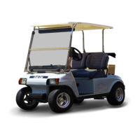
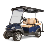
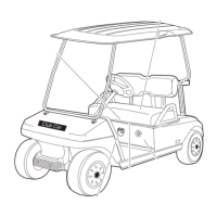
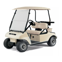
EasyManua.ls Logo

Club Car Gasoline User Manual

Club Car Gasoline
544 pages
To Next Page IconTo Next Page
Page #1 background imageLoading...
Page #1 background image
DS GOLF CARS
GASOLINE/ELECTRIC
MANUAL NUMBER 101905101
EDITION CODE 1196H0799C
MAINTENANCE
SERVICE
1995-1996

Table of Contents

Questions and Answers:

Club Car Gasoline Specifications

General IconGeneral
BrandClub Car
ModelGasoline
CategoryGolf Cars
LanguageEnglish

Summary

Section 1 - Safety

Section 2 - Vehicle Specifications

Power Source

Details on the power source for different Club Car DS models, including engine and drive motor specifications.

Steering/Suspension/Brakes

Specifications for steering, suspension, and brake systems of Club Car DS Golf Cars.

Body/Chassis

Specifications related to the body and chassis construction of Club Car DS Golf Cars.

Seating Capacity/Fuel Capacity

Information on standard and fairway villager seating capacities and fuel tank specifications.

Dimensions/Weight

Detailed dimensions and weight specifications for various Club Car DS Golf Car models.

Section 3 - General Information

Model Identification

Information on how to identify your Club Car by its serial number and data plate location.

Safety Committee

Recommendations for appointing a safety committee for golf car fleets and their primary concerns.

Pre-Operation Checklist

A checklist for inspecting a new Club Car before accepting delivery, covering general parts, labels, and tires.

Performance Inspection

Procedure for test driving the vehicle to check brakes, park brake, steering, accelerator, and speed.

Controls

Explanation of the vehicle's controls including the key switch, forward/reverse control, and accelerator pedal.

Forward and Reverse Control

Instructions for operating the forward and reverse controls on DS Gasoline, V-Glide, and PowerDrive models.

Accelerator Pedal

Details on the operation of the accelerator pedal and its function in starting and controlling the vehicle.

Brake Pedal

Description of the brake pedal and park brake pedal operation for stopping and parking the vehicle.

Neutral Lock-out

Explanation of the neutral lock-out circuit in gasoline vehicles that prevents starting in neutral.

Choke

Location and operation of the choke for starting the engine in cool or cold temperatures.

Oil Light

Information on the low oil warning light for gasoline vehicles and its function.

Battery Warning Light

Explanation of the dash-mounted warning light for PowerDrive System 48 vehicles indicating battery status.

Driving Instructions

Instructions for safe operation, starting, driving, stopping, and parking the vehicle.

Towing

Guidelines and warnings for towing Club Car vehicles, including tow bar usage and speed limits.

Transporting on a Trailer

Warnings and guidelines for transporting the vehicle on a trailer, including securing the vehicle.

Storage - Gasoline Vehicle

Procedure for preparing a gasoline vehicle for extended off-season storage.

Storage - Electric Vehicle

Procedure for preparing electric vehicles for extended off-season storage, including battery care.

Section 4 - Periodic Maintenance

Lubrication - Gasoline Vehicles

Periodic lubrication schedule for gasoline vehicles, detailing service, place, and recommended lubricant.

Lubrication - Electric Vehicles

Periodic lubrication schedule for electric vehicles, detailing service, place, and recommended lubricant.

Vehicle Capacities

Specifications for vehicle capacities including engine crankcase, transmission, drive unit, and fuel tank.

Periodic Service - Gasoline Vehicles

Schedule for daily, weekly, monthly, and semi-annual owner service for gasoline vehicles.

Periodic Service - Electric Vehicles

Schedule for daily, weekly, monthly, quarterly, and semi-annual owner service for electric vehicles.

Section 5 - Body and Trim

General Information

Information on cleaning and maintaining the injection molded Armorflex body panels of Club Car vehicles.

Front and Rear Body Repair

Procedures for repairing stress lines, deformation, large scratches, abrasions, gouges, punctures, and tears in body panels.

Front Body

Details on the removal and installation of the front body panel of Club Car vehicles.

Rear Body

Instructions for the removal and installation of the rear body panel on Club Car vehicles.

Section 6 - Accelerator and Brake Pedal Group

Pedal Group Adjustment - Early 1995 Vehicles

Procedures for adjusting the brake pedal height, cables, and accelerator rod for early 1995 models.

Pedal Group Adjustment - Late 1995 and 1996 Vehicles

Procedures for adjusting the brake pedal height for late 1995 and 1996 Club Car models.

Pedal Group Disassembly and Assembly - Early 1995 Vehicles

Step-by-step instructions for disassembling and assembling the brake pedal and park brake assemblies.

Pedal Group Disassembly and Assembly - Late 1995 and 1996 Vehicles

Instructions for disassembling and assembling the pedal group for late 1995 and 1996 models.

Section 7 - Wheel Brake Assemblies

Removal of Brake Shoes and Cleaning of Wheel Brake Assemblies

Instructions for removing brake shoes and cleaning the brake assembly, including safety warnings.

Installing the Brake Shoes

Step-by-step guide for installing brake shoes, including spring attachment and shoe positioning.

Adjusting the Brakes

Procedure for adjusting the brakes after cleaning or repair, including free play adjustment.

Brake Assembly

Instructions for removing the brake assembly from the axle tube and installing it.

Section 8 - Steering and Front Suspension

General Information - Steering

Overview of the steering system, controlled by a rack and pinion assembly.

Steering Wheel

Procedure for removing and installing the steering wheel, including lubrication notes.

Steering Column

Instructions for removing and installing the steering column assembly.

Steering Adjustment

Procedure for adjusting the steering gear, including checking alignment and turning radius.

Rack and Pinion

Information regarding the rack and pinion steering system.

Rack and Pinion Removal

Step-by-step instructions for removing the rack and pinion assembly.

Rack and Pinion Disassembly

Detailed instructions for disassembling the rack and pinion assembly.

Tie Rod and Drag Link

Information on the tie rod and drag link system.

Tie Rod and Drag Link Removal

Procedure for removing the tie rod and drag link assembly.

Tie Rod and Drag Link Installation

Instructions for installing the tie rod and drag link assembly.

Front Suspension

Overview of the front suspension system.

Lubrication

Lubrication points and schedule for the front suspension and steering linkages.

Wheel Alignment

Procedures for adjusting camber and toe-in of the front wheels and drag link adjustment.

Camber Adjustment

Steps for adjusting the camber angle of each front wheel.

Toe-in Adjustment

Procedure for adjusting the toe-in of the front wheels.

Front Suspension Components

Description and removal/installation procedures for front suspension components.

Tapered Leaf Spring Removal

Instructions for removing the tapered leaf springs from the vehicle.

Tapered Leaf Spring Installation

Instructions for installing the tapered leaf springs.

King Pin and Steering Spindle Removal

Procedure for removing the king pin and steering spindle components.

King Pin and Steering Spindle Installation

Instructions for installing the king pin and steering spindle components.

Front Wheel Bearings and Hubs

Procedures for checking free play and removing/installing front wheel bearings and hubs.

Check Front Wheel Free Play

Steps to check for any observable rocking of the wheel on the hub.

Front Wheel Bearings and Hub Removal

Instructions for removing the front wheels and front wheel hubs.

Section 9 - Transaxle

Lubrication

Information on the location of lubrication plugs and the proper procedure for filling the transaxle.

Axle Shaft

Procedure for removing and installing the axle shaft, including retaining rings and bearings.

Axle Bearing

Instructions for removing and installing the axle bearing, including inspection.

Removing the Transaxle

Step-by-step instructions for removing the transaxle from DS Gasoline and DS Electric vehicles.

Removing the Transaxle - DS Gasoline

Detailed procedure for removing the transaxle from gasoline-powered DS models.

Removing the Transaxle - DS Electric

Detailed procedure for removing the transaxle from electric DS models.

Disassembly, Inspection, and Assembly of the Transaxle

Procedures for disassembling, inspecting, and reassembling the transaxle.

Shimming the Transaxle

Procedure for determining and installing shims if the transaxle housing or axle tube has been replaced.

Installation of the Transaxle

Instructions for installing the transaxle assembly back into the vehicle for both gasoline and electric models.

Section 10 - Wheels and Tires

General Information

Importance of proper wheel and tire care for maximum tire life and vehicle handling.

Wheel Removal

Procedure for removing the wheel and tire assembly from the vehicle.

Wheel Installation

Instructions for installing wheels onto the vehicle, including tightening lug nuts.

Removing the Tire from the Rim

Steps for removing a tire from the wheel rim, including when a tire machine is not available.

Repairing a Tire

Procedure for determining the location and cause of an air leak in a tire.

Installing the Tire on the Rim

Instructions for installing a tire onto the rim, including cleaning beads and inflating.

Section 11 - Troubleshooting the Gasoline Vehicle

Troubleshooting Guide

A checklist to help identify operating difficulties, including symptoms, causes, and suggested checks.

Section 12 - Electrical System Gasoline Vehicles

General Information

Overview of the 12-volt DC negative ground electrical system and its seven circuits.

FE 290 Gasoline Vehicle Electrical Circuit

Diagram and explanation of the electrical circuit for the FE 290 gasoline engine.

The Starter Circuit

Explanation of the starter circuit's function, independence from ignition, and power source.

The Generator Circuit

Description of the generator circuit, including starter/generator, voltage regulator, and battery.

Engine Ignition Circuit

Details on the engine ignition circuit, consisting of igniter, coil, spark plug, and RPM limiter.

Engine Kill Circuit

Explanation of the engine kill circuit's function and components for stopping the engine.

Reverse Buzzer Circuit

Information on the reverse buzzer as a safety warning device activated in reverse.

Low Oil Warning Circuit

Description of the low oil warning circuit, including oil sending unit and dash-mounted light.

Neutral Lock-out Circuit

Explanation of the neutral lock-out circuit that prevents starting in neutral.

Circuit Testing

Procedures for testing the entire electrical system without major disassembly.

Test Procedure 1 - Batteries/Voltage Check

Procedure for testing vehicle battery voltage and checking connections.

Test Procedure 2 - Key Switch

Procedure for testing the key switch for continuity in different positions.

Test Procedure 3 - Forward and Reverse Anti-Arcing Limit Switch

Procedure for testing the F&R anti-arcing limit switch for continuity.

Test Procedure 4 - Accelerator Pedal Limit Switch

Procedure for testing the accelerator pedal limit switch.

Test Procedure 5 - Solenoid Activating Coil

Procedure for testing the solenoid activating coil.

Test Procedure 6 - Resistors

Procedure for testing the resistors for loose connections or damage.

Test Procedure 7 - Starter/Generator (Starter Function)

Procedure for testing the starter function of the starter/generator.

Test Procedure 8 - Wire Continuity

Procedure for testing wire continuity.

Test Procedure 9 - Starter/Generator (Generator Function)

Procedure for testing the generator function of the starter/generator.

Test Procedure 10 - Voltage Regulator

Procedure for testing the voltage regulator.

Test Procedure 11 - Ignition Spark

Procedure for testing ignition spark.

Test Procedure 12 - Igniter

Procedure for testing the igniter on vehicles before serial number AG9624-502638.

Test Procedure 13 - RPM Limiter

Procedure for testing the RPM limiter.

Test Procedure 14 - Ignition Coil

Procedure for testing the ignition coil.

Test Procedure 15 - Disconnected Kill Wire

Procedure for testing the engine kill circuit when the white/black wire is disconnected.

Test Procedure 16 - Kill Limit Switch

Procedure for testing the kill limit switch.

Test Procedure 17 - Key Switch (Engine Kill Circuit)

Procedure for testing the key switch's function in the engine kill circuit.

Test Procedure 18 - Reverse Buzzer Limit Switch

Procedure for testing the reverse buzzer limit switch.

Test Procedure 19 - Reverse Buzzer

Procedure for testing the reverse buzzer.

Test Procedure 20 - Oil Sending Unit

Procedure for testing the oil sending unit.

Test Procedure 21 - Oil Warning Light

Procedure for testing the oil warning light circuit.

Test Procedure 22 - Key Switch (Starter Circuit)

Procedure for testing the key switch's function in the starter circuit.

Test Procedure 23 - Neutral Lock-out Cam

Check to ensure neutral lock-out cam lobes depress the limit switch lever correctly.

Starter/Generator

Information on the starter/generator, including removal and disassembly procedures.

Removal of the Starter/Generator

Step-by-step instructions for removing the starter/generator from the vehicle.

Disassembly of the Starter/Generator to Service the Brushes

Procedure for disassembling the starter/generator to service or replace the brushes.

Cleaning, Inspection, and Replacement of Brushes

Instructions for inspecting and replacing starter/generator brushes and springs.

Assembly of the Starter/Generator

Steps for assembling the starter/generator after servicing components like brushes and springs.

Disassembly of the Starter/Generator to Service the Armature/Commutator

Procedure for disassembling the starter/generator to service the armature and commutator.

Visual Inspection of Armature

Guide to visually inspecting the armature for defects like frayed insulation or worn commutators.

Cleaning, Inspection, and Replacement of the Commutator

Instructions for cleaning, inspecting, and replacing the commutator and bearings.

Armature Ground Test

Procedure for testing the armature for ground faults using a multimeter.

Visual Inspection of Windings

Inspection of motor windings for signs of overheating or damage.

Inspection of Motor Components

Inspection of insulators, brushes, and brush springs for wear or damage.

Motor Installation

Step-by-step instructions for installing the motor onto the transaxle.

Section 13 - FE 290 Engine

General Information

Overview of the FE 290 engine, its cycle, cooling, and major component assemblies.

Special Tools

List of required special tools for engine service, with part numbers.

Before Servicing

Important information and instructions to read before beginning engine service.

Mechanical Systems

Information on engine adjustments and edges.

Dirt

Instruction to clean the engine thoroughly before servicing.

Tightening Sequence

Guidelines for tightening bolts, nuts, and screws in the proper order and method.

Torque

Adherence to torque values for assembly and disassembly is crucial for preventing damage.

Force

Guidance on using common sense for force in assembly/disassembly and using specific tools.

Lubricant

Information on the proper application of oils and greases for engine lubrication.

Lubrication

Advice on engine wear during warm-up and applying lubricant to rubbing surfaces.

Press

Guidance on installing parts like seals using a press or driver.

Oil Seal, Grease Seal

Instructions for replacing oil or grease seals and using a seal guide.

Gasket, O-Ring

Advice to replace gaskets or O-Rings if in doubt about their condition to avoid leaks.

Liquid Gasket and Non-permanent Locking Agent

Directions for using liquid gasket and non-permanent locking agents, including application advice.

Ball Bearing Installation

Procedure for installing ball bearings using a suitable driver to prevent damage.

Circlip, Retaining Ring

Instructions for replacing circlips and retaining rings, emphasizing careful installation.

High Flash-point Solvent

Recommendation for using a high flash-point solvent for cleaning, with examples.

Molybdenum Disulfide (MoS2) Grease

Reference to using MoS2 grease in engine and chassis parts, with manufacturer recommendations.

Engine Rotation

Guidance on the correct direction for turning the crankshaft by hand during engine assembly.

Electrical System

General advice for working on electrical equipment, emphasizing safety and proper procedures.

Lubrication System

Explanation of the pressurized lubrication system components and their functions.

Spark Plug

Information on spark plug selection, gap setting, and inspection.

Removing the Spark Plug

Procedure for removing the spark plug from the engine head.

Spark Plug Cleaning, Inspection and Repair

How to examine the spark plug for deposits and determine engine condition.

Testing the Spark Plug

Procedure for testing the spark plug, including setting the spark gap.

Installing the Spark Plug

Instructions for installing the spark plug, including gasket and torque specifications.

Engine Mounting Plate and Inner Frame

Information regarding the engine mounting plate and inner frame.

Cylinder Head

General information on the cylinder head, including compression testing.

Cylinder Shroud Removal

Procedure for removing the cylinder shroud, including disconnecting fuel lines and removing manifold.

Rocker Arms and Push Rods Removal

Instructions for removing rocker arms, push rods, rocker cover, and breather tube.

Cylinder Head / Valves Removal

Procedure for removing the cylinder head assembly and its components.

Valve Guides

Inspection and replacement procedures for valve guides.

Valve Seats

Inspection and repair procedures for valve seats.

Valve Seat Repair

Steps for reconditioning valve seats using specialized cutters.

Valves

Visual inspection of valves for wear, discoloration, or stem damage.

Valve Head Thickness

Procedure for measuring valve head thickness and checking against service limits.

Valve Stem Bend

Instructions for measuring valve stem bend and replacing if it exceeds service limits.

Stem Diameter

Procedure for measuring valve stem diameter and checking against service limits.

Valve Springs

Inspection of valve springs for damage and measurement of free length.

Rocker Arms and Rocker Shaft

Inspection of rocker arm bearings and rocker shaft for wear.

Push Rods

Procedure for inspecting push rods for bend and replacing if necessary.

Cylinder Head Installation

Steps for installing the cylinder head assembly, including rocker arms and push rods.

Breather Valve (Reed Valve)

Information on the breather valve's function and removal procedure.

Breather Valve (Reed Valve) Removal

Procedure for removing the breather valve (reed valve) assembly.

Cleaning and Inspection of Cylinder Head

Instructions for cleaning and inspecting the cylinder head.

Crankshaft Installation

Procedure for installing the crankshaft, including gears and link rods.

Piston/Connecting Rod

Procedures for removing, inspecting, and installing the piston and connecting rod assembly.

Piston

Inspection and repair procedures for the piston, including cleaning and ring groove checks.

Piston Pin

Inspection procedures for the piston pin and piston pin hole.

Connecting Rod

Inspection procedures for connecting rod bearing surfaces and bolts.

Connecting Rod Inspection

How to inspect connecting rod bearing surfaces and measure bore diameters.

Cylinder Block

Inspection of the cylinder block for damage such as cracks or scoring.

To Resize Bore to Next Oversize

Instructions for resizing the cylinder bore to the next oversize dimension.

Link Rod Inspection

Procedure for inspecting link rod bearing surfaces for wear or damage.

Link Rod Bushing Replacement

Steps for replacing the link rod bushing.

Counterbalance Weight

Inspection of the counterbalance weight bearing surface and bore.

Section 14 - Fuel System

General Information

Overview of the fuel system, including carburetor, fuel filters, lines, and tank vent.

How the Carburetor Works

Explanation of the carburetor's main system, slow speed system, and choke/fresh air system.

Main System

Description of the carburetor's main system components and their function in fuel metering.

Slow Speed System

Explanation of the slow speed system's function in supplying fuel during low speed running.

Standard Jetting

Standard jet sizes for pilot air screw, pilot jet, main jet, and throttle stop screw.

Choke and Fresh Air System

How the choke system aids in starting a cold engine by creating a fuel-rich mixture.

Float System

Explanation of the float system that maintains correct fuel level in the carburetor's float chamber.

Carburetor

Check of fuel and ignition systems before suspecting carburetor issues.

Main Jet Elevation/Size Chart

Chart listing elevation ratings for various main jet sizes for optimal engine performance.

Procedure for Changing Main Jet

Step-by-step procedure for removing and installing the main jet in the carburetor.

Accelerator Rod

Procedure for removing and installing the accelerator rod.

Accelerator Rod Removal

Instructions for removing the accelerator rod by disconnecting ball joints and bell cranks.

Accelerator Rod Installation and Adjustment

Steps for installing and adjusting the accelerator rod for proper throttle cable cam position.

Governor Cable

Procedure for removing and installing the governor cable, including adjustment.

Removing the Governor Cable

Instructions for removing the governor cable from the vehicle.

Governor Cable Installation and Adjustment

Steps for installing and adjusting the governor cable for proper operation.

Accelerator Cable

Instructions for removing and installing the accelerator cable.

Closed Throttle Adjustment

Procedure for adjusting the idle speed when the accelerator pedal is released.

Engine RPM Adjustment

Procedure for adjusting the engine RPM to the specified high speed.

Choke and Intake System

Information on the choke system for cold starts and the air filter housing.

Choke and Intake System Removal

Procedure for removing the choke assembly and intake hose.

Choke and Intake System Installation

Instructions for installing the choke assembly and intake hose.

Air Filter Element

General information on the air filter element, including service intervals and replacement.

Fuel Filters

General information on fuel filters, including inspection and replacement guidelines.

Removing the Fuel Filters

Procedure for removing the primary and secondary fuel filters.

Fuel Pump

General information on the impulse fuel pump and troubleshooting steps.

Fuel Pump Removal

Instructions for removing the fuel pump from the engine compartment.

Fuel Pump Disassembly

Procedure for disassembling the fuel pump for cleaning and inspection.

Cleaning and Inspection of the Fuel Pump

Steps for cleaning and inspecting fuel pump components for damage.

Fuel Pump Assembly

Instructions for assembling the fuel pump.

Fuel Pump Installation

Procedure for installing the fuel pump onto the fuel tank.

Fuel Tank

General information on the fuel tank, including off-season storage preparation.

Fuel Tank Removal

Procedure for removing the fuel tank from the vehicle.

Fuel Tank Disposal

Instructions for safely disposing of or recycling the fuel tank.

Fuel Tank Storage

Guidelines for storing the fuel tank during off-season.

Fuel Tank Installation

Procedure for installing the fuel tank into the vehicle.

Section 15 - Exhaust System

General Information

Overview of the exhaust system designed for quiet vehicle operation.

Muffler

Instructions for removing and installing the muffler and bracket assembly.

Removing The Muffler

Step-by-step procedure for removing the muffler and bracket assembly from the vehicle.

Installing The Muffler

Instructions for installing the muffler and bracket assembly, including clamp and gasket replacement.

Section 16 - Torque Converter

General Information

Overview of the torque converter system, including drive clutch, driven clutch, and drive belt.

Troubleshooting

Guide to troubleshooting torque converter and drive belt issues.

Drive Belt

Inspection and replacement guidelines for the drive belt.

Removing the Drive Belt

Procedure for removing the drive belt from the drive and driven clutches.

Installing the Drive Belt

Instructions for installing a new drive belt onto the drive and driven clutches.

Drive Clutch

Information on servicing the drive clutch, including warnings and precautions.

Drive Clutch Removal

Step-by-step instructions for removing the drive clutch assembly.

Cleaning and Inspection of the Drive Clutch

Procedure for cleaning and inspecting drive clutch parts for wear or damage.

Drive Clutch Disassembly

Detailed instructions for disassembling the drive clutch assembly.

Inspection of Drive Clutch Parts

Inspection of drive clutch parts including cam, buttons, sheaves, shaft, and bearings.

Drive Clutch Assembly

Instructions for assembling the drive clutch, including bearing, spring, and spacer installation.

Driven Clutch Installation

Procedure for installing the driven clutch assembly.

Clutch Alignment

Procedure for checking and adjusting clutch alignment using a clutch alignment tool.

Section 17 - Transmission and Governor

General Information

Overview of the transmission system, power transfer, and gear selection.

Lubrication

Information on transmission lubrication, including plug locations and lubricant type.

Removal of the Transmission

Step-by-step instructions for removing the transmission from the vehicle.

Disassembly of the Transmission

Detailed instructions for disassembling the transmission housing and its components.

Governor Disassembly

Procedure for disassembling the governor assembly.

Main Cluster Disassembly

Instructions for disassembling the main cluster assembly.

Clutch Hub Disassembly

Procedure for disassembling the clutch hub assembly.

Input Shaft Disassembly

Instructions for disassembling the input shaft.

Shift Arm Disassembly

Procedure for disassembling the shifter arm.

Transmission Housing Disassembly

Instructions for disassembling the transmission housing.

Section 18 - Rear Suspension

Gasoline Vehicle

General information about the rear suspension of the DS gasoline vehicle.

Shock Absorbers

Procedure for inspecting and removing shock absorbers.

Inspecting and Removing Shock Absorbers

Steps to check shock absorbers for fluid leakage and remove them.

Installing Shock Absorbers

Instructions for installing shock absorbers.

Mono-Leaf Springs

Procedure for removing and installing the mono-leaf springs.

Removing the Mono-Leaf Springs

Step-by-step instructions for removing the mono-leaf springs.

Installing the Mono-Leaf Springs

Instructions for installing the mono-leaf springs.

The Snubber

Procedure for removing and installing the snubber.

Removing the Snubber

Steps for removing the snubber from the vehicle.

Installing the Snubber

Instructions for installing the new snubber.

Section 19 A - Electrical System V-Glide 36 Volt Vehicle

General Information

Overview of the V-Glide 36 volt vehicle's electrical circuitry and components.

V-Glide Electrical Circuits

Explanation of the three separate circuits: control, power, and charge, plus reverse buzzer.

The Control Circuit

Components of the control circuit: key switch, limit switches, solenoid, and wires.

The Power Circuit

Components of the power circuit: speed controller, solenoid, motor, batteries, and wiring.

The Speed Control Circuit

Explanation of the speed control circuit for multi-step and continuously variable potentiometer models.

Multi-step Potentiometer (Wiper Switch) Models

How the speed control circuit works with multi-step potentiometers.

Continuously Variable Potentiometer Models

How the speed control circuit works with continuously variable potentiometers.

The Charge Circuit

Components of the charge circuit: OBC, charger, plug, receptacle, fuse link, and batteries.

Troubleshooting V-Glide Troubleshooting Guide

A guide to troubleshooting common problems encountered with V-Glide vehicles.

Diagnostic Reference Charts

Reference charts for diagnosing specific failures in the electrical system.

Test Procedure 1 - Batteries/Voltage Check

Procedure for testing vehicle battery voltage and checking connections.

Test Procedure 2 - Key Switch

Procedure for testing the key switch for continuity.

Test Procedure 3 - Forward and Reverse Anti-Arcing Limit Switch

Procedure for testing the F&R anti-arcing limit switch for continuity.

Test Procedure 4 - Accelerator Pedal Limit Switch

Procedure for testing the accelerator pedal limit switch.

Test Procedure 7 - Starter/Generator (Starter Function)

Procedure for testing the starter function of the starter/generator.

Test Procedure 8 - Wire Continuity

Procedure for testing wire continuity.

Test Procedure 9 - Starter/Generator (Generator Function)

Procedure for testing the generator function of the starter/generator.

Test Procedure 10 - Voltage Regulator

Procedure for testing the voltage regulator.

Test Procedure 11 - Ignition Spark

Procedure for testing ignition spark.

Test Procedure 12 - Igniter

Procedure for testing the igniter on vehicles before serial number AG9624-502638.

Test Procedure 13 - RPM Limiter

Procedure for testing the RPM limiter.

Test Procedure 14 - Ignition Coil

Procedure for testing the ignition coil.

Test Procedure 15 - Disconnected Kill Wire

Procedure for testing the engine kill circuit when the white/black wire is disconnected.

Test Procedure 16 - Kill Limit Switch

Procedure for testing the kill limit switch.

Test Procedure 17 - Key Switch (Engine Kill Circuit)

Procedure for testing the key switch's function in the engine kill circuit.

Test Procedure 18 - Reverse Buzzer Limit Switch

Procedure for testing the reverse buzzer limit switch.

Test Procedure 19 - Reverse Buzzer

Procedure for testing the reverse buzzer.

Test Procedure 20 - Oil Sending Unit

Procedure for testing the oil sending unit.

Test Procedure 21 - Oil Warning Light

Procedure for testing the oil warning light circuit.

Test Procedure 22 - Key Switch (Starter Circuit)

Procedure for testing the key switch's function in the starter circuit.

Test Procedure 23 - Neutral Lock-out Cam

Check to ensure neutral lock-out cam lobes depress the limit switch lever correctly.

Section 19B - Electrical Components, PowerDrive Plus Vehicles

Key Switch

Information on the key switch location and testing procedures.

Testing the Key Switch

Procedure for testing the key switch.

Removing the Key Switch

Step-by-step instructions for removing the key switch from the center dash.

Forward and Reverse Switch

Information on the forward and reverse switch, including testing and removal.

Testing the Forward and Reverse (F&R) Switch

Procedure for testing the forward and reverse switch.

Removing the Forward and Reverse (F&R) Switch

Instructions for removing the forward and reverse switch.

Servicing the Forward and Reverse (F&R) Switch

Tips for servicing the forward and reverse switch, including cleaning and lubrication.

Installing the Forward and Reverse (F&R) Switch

Procedure for installing the forward and reverse switch.

Forward and Reverse (F&R) Limit Switches

Information on the F&R anti-arcing, reverse buzzer, and half-speed reverse limit switches.

Testing the Limit Switches

Procedures for testing the F&R anti-arcing, reverse buzzer, and half-speed reverse limit switches.

Removing the Limit Switches

Instructions for removing the limit switches from the F&R switch.

Installing Limit Switches

Steps for installing the limit switches onto the F&R switch.

Accelerator Pedal Limit Switch

Information on the accelerator pedal limit switch, including testing and removal.

Testing the Accelerator Pedal Limit Switch

Procedure for testing the accelerator pedal limit switch.

Removing the Accelerator Pedal Limit Switch

Instructions for removing the accelerator pedal limit switch.

Installing the Accelerator Pedal Limit Switch

Procedure for installing the accelerator pedal limit switch.

The Solenoid

Information on the solenoid, including testing, removal, and installation.

Testing the Solenoid

Procedures for testing the solenoid.

Removing the Solenoid

Instructions for removing the solenoid.

Installing the Solenoid

Procedure for installing the solenoid.

Resistors

Information on resistors attached to the resistor mounting board.

Testing the Resistors

Procedure for testing the resistors.

Removing the Resistors

Instructions for removing the resistors.

Installing the Resistors

Procedure for installing the resistors.

V-GLIDE WIPER SWITCH

Information on the V-Glide wiper switch, including inspection and adjustments.

V-Glide Wiper Switch Arm Adjustment

Procedure for adjusting the V-Glide wiper switch arm and contacts for proper operation.

Section 20 A - Electrical System, PowerDrive System 48

General Information

Overview of the PowerDrive System 48 electrical system and components.

The On-Board Computer (OBC)

Function of the OBC in controlling the charger and monitoring battery usage.

PowerDrive Vehicle Electrical Circuits

Description of the four separate circuits in the PowerDrive System 48 vehicle.

Troubleshooting Guide

Diagnostic reference charts for troubleshooting PowerDrive System 48 vehicle symptoms.

Diagnostic Reference Charts

Charts for system troubleshooting, with detailed test instructions.

PowerDrive System 48 Troubleshooting Guide

Guide to troubleshooting common problems with PowerDrive System 48 vehicles.

Circuit Testing

Procedures for testing the electrical system without major disassembly.

Control Circuit

Explanation of the control circuit components and functions.

Test Procedure 1 - Batteries/Voltage Check

Procedure for testing vehicle battery voltage and checking connections.

Test Procedure 2 - Key Switch

Procedure for testing the key switch for continuity.

Test Procedure 3 - Forward/Reverse Anti-Arcing Limit Switch

Procedure for testing the F&R anti-arcing limit switch.

Test Procedure 4 - Accelerator Pedal Limit Switch

Procedure for testing the accelerator pedal limit switch.

Test Procedure 5 - Solenoid Activating Coil

Procedure for testing the solenoid activating coil.

Test Procedure 6 - Forward/Reverse Switch

Procedure for testing the forward and reverse switch.

Test Procedure 7 - Solenoid Contacts (Power Off)

Procedure for testing solenoid contacts with power off.

Test Procedure 8 - Multi-step Potentiometer

Procedure for testing the multi-step potentiometer.

Test Procedure 9 - Continuously Variable Potentiometer

Procedure for testing the continuously variable potentiometer.

Test Procedure 10 - Solid State Speed Controller

Procedure for testing the solid state speed controller.

Test Procedure 11 - On-board Computer Lockout Circuit

Procedure for testing the on-board computer lockout circuit.

Test Procedure 12 - Half-speed Reverse Limit Switch (F&R Limit Switch No. 3)

Procedure for testing the half-speed reverse limit switch.

Test Procedure 13 - Half-speed Reverse Resistor

Procedure for testing the half-speed reverse resistor.

The Communication Display Module (CDM)

Information on using the CDM to retrieve data from the on-board computer.

Communication Display Module Troubleshooting Guide

Troubleshooting guide for issues with the CDM and on-board computer.

Section 20 B - Electrical Components, PowerDrive System 48 Vehicle

Key Switch

Information on the key switch location and testing procedures.

Testing the Key Switch

Procedure for testing the key switch.

Removing the Key Switch

Step-by-step instructions for removing the key switch.

Forward and Reverse Switch

Information on the forward and reverse switch, including testing and removal.

Testing the Forward and Reverse (F&R) Switch

Procedure for testing the forward and reverse switch.

Removing the Forward and Reverse (F&R) Switch

Instructions for removing the forward and reverse switch.

Servicing the Forward and Reverse (F&R) Switch

Tips for servicing the forward and reverse switch.

Installing the Forward and Reverse (F&R) Switch

Procedure for installing the forward and reverse switch.

Forward and Reverse (F&R) Limit Switches

Information on F&R anti-arcing, reverse buzzer, and half-speed reverse limit switches.

Testing the Limit Switches

Procedures for testing the F&R limit switches.

Removing the Limit Switches

Instructions for removing the limit switches.

Installing Limit Switches

Steps for installing the limit switches.

Accelerator Pedal Limit Switch

Information on the accelerator pedal limit switch, including testing and removal.

Testing the Accelerator Pedal Limit Switch

Procedure for testing the accelerator pedal limit switch.

Removing the Accelerator Pedal Limit Switch

Instructions for removing the accelerator pedal limit switch.

Installing the Accelerator Pedal Limit Switch

Procedure for installing the accelerator pedal limit switch.

The Solenoid

Information on the solenoid, including testing, removal, and installation.

Testing the Solenoid

Procedures for testing the solenoid.

Removing the Solenoid

Instructions for removing the solenoid.

Installing the Solenoid

Procedure for installing the solenoid.

Resistors

Information on resistors attached to the resistor mounting board.

Testing the Resistors

Procedure for testing the resistors.

Removing the Resistors

Instructions for removing the resistors.

Installing the Resistors

Procedure for installing the resistors.

V-GLIDE WIPER SWITCH

Information on the V-Glide wiper switch, including inspection and adjustments.

V-Glide Wiper Switch Arm Adjustment

Procedure for adjusting the V-Glide wiper switch arm and contacts.

Section 21 A - Electrical System, PowerDrive Plus Vehicles

General Information

Overview of the PowerDrive Plus vehicle's electrical system.

Key Switch

Information on the key switch location and testing procedures.

Testing the Key Switch

Procedure for testing the key switch.

Removing the Key Switch

Step-by-step instructions for removing the key switch.

The Control Circuit

Components of the control circuit: capacitor charge, solenoid control, F&R control, etc.

The Z Plug

Explanation of the Z plug connectors and their functions.

Capacitor Charge Circuit

How the capacitor charge circuit maintains constant voltage for the speed controller.

Main Solenoid Control Circuit

Circuit that supplies voltage to the solenoid activating coil.

Forward and Reverse Control Circuit

Circuit that controls the selection of forward or reverse vehicle movement.

Controller Activating Circuit

Circuit that supplies voltage to the Z plug/controller to activate it.

Motor Braking Control Circuit

Circuit activated by dynamic braking solenoid for motor braking functions.

Speed Control Circuit

How the controller regulates vehicle ground speed by varying voltage pulses to the motor.

Test Procedure 8 - Multi-step Potentiometer

Procedure for testing the multi-step potentiometer.

Test Procedure 9 - Continuously Variable Potentiometer

Procedure for testing the continuously variable potentiometer.

Test Procedure 22 - Voltage at Z3 (Orange/White Wire) Position In Z Plug

Procedure for checking voltage at Z3 (orange/white wire) position in Z plug.

Test Procedure 23 - Continuity of the Z3 Orange/White Wire

Procedure for checking continuity of the Z3 orange/white wire.

Test Procedure 24 - Voltage to Dynamic Braking Solenoid Coil

Procedure for checking voltage to the dynamic braking solenoid coil.

Test Procedure 25 - Solenoid to Solenoid Red Wire Continuity

Procedure for checking continuity of the solenoid to solenoid red wire.

Test Procedure 26 - Voltage from Z5 (Brown Wire) to Dynamic Braking Solenoid Coil

Procedure for checking voltage from Z5 (brown wire) to the dynamic braking solenoid coil.

Test Procedure 27 - Dynamic Braking Solenoid Brown Wire Continuity

Procedure for checking continuity of the dynamic braking solenoid brown wire.

Test Procedure 30 - Energy Displacement Module Condition and 6 Gauge Green Wire Continuity

Procedure for checking energy displacement module condition and green wire continuity.

Test Procedure 31 - Battery Warning Light Circuit

Procedure for testing the battery warning light circuit.

Test Procedure 32 - Potentiometer Voltage Output Test

Procedure for testing the potentiometer voltage output.

Test Procedure 33 - Voltage at Z9 (Yellow Wire) and Z10 (Purple Wire) Positions

Procedure for checking voltage at Z9 and Z10 positions in Z plug.

Test Procedure 34 - Z9 (Yellow Wire) and Z12 (Yellow Wire) Continuity

Procedure for checking continuity of Z9 (yellow) and Z12 (yellow) wires.

Test Procedure 35 - 3-Wire Plug on the Potentiometer

Procedure for checking the 3-wire plug on the potentiometer.

Test Procedure 36 - Voltage from Controller to Motor

Procedure for checking voltage from controller to motor.

Test Procedure 38 - Continuity of Motor Wires

Procedure for checking continuity of motor wires.

Test Procedure 39 - Motor Speed Sensor Voltage Output

Procedure for checking motor speed sensor voltage output.

Test Procedure 40 - Controller Voltage to Speed Sensor Plug (Z13 Red Wire and Z14 Green Wire)

Procedure for checking voltage from controller to speed sensor plug.

Test Procedure 41 - Z13 (Red Wire) and Z14 (Green Wire) Continuity

Procedure for checking continuity of Z13 (red wire) and Z14 (green wire).

Test Procedure 42 - Motor Sensor 3-Wire Plug Connection

Procedure for checking the motor sensor 3-wire plug connection.

Section 21 B - Electrical Components, PowerDrive Plus Vehicles

Key Switch

Information on the key switch location and testing procedures.

Testing the Key Switch

Procedure for testing the key switch.

Removing the Key Switch

Step-by-step instructions for removing the key switch.

Forward and Reverse Switch

Information on the forward and reverse switch, including testing and removal.

Testing the Forward and Reverse (F&R) Switch

Procedure for testing the forward and reverse switch.

Removing the Forward and Reverse (F&R) Switch

Instructions for removing the forward and reverse switch.

Servicing the Forward and Reverse (F&R) Switch

Tips for servicing the forward and reverse switch.

Installing the Forward and Reverse (F&R) Switch

Procedure for installing the forward and reverse switch.

Forward and Reverse (F&R) Limit Switches

Information on F&R anti-arcing, reverse buzzer, and half-speed reverse limit switches.

Testing the Limit Switches

Procedures for testing the F&R limit switches.

Removing the Limit Switches

Instructions for removing the limit switches.

Installing Limit Switches

Steps for installing the limit switches.

Accelerator Pedal Limit Switch

Information on the accelerator pedal limit switch, including testing and removal.

Testing the Accelerator Pedal Limit Switch

Procedure for testing the accelerator pedal limit switch.

Removing the Accelerator Pedal Limit Switch

Instructions for removing the accelerator pedal limit switch.

Installing the Accelerator Pedal Limit Switch

Procedure for installing the accelerator pedal limit switch.

The Solenoid

Information on the solenoid, including testing, removal, and installation.

Testing the Solenoid

Procedures for testing the solenoid.

Removing the Solenoid

Instructions for removing the solenoid.

Installing the Solenoid

Procedure for installing the solenoid.

Resistors

Information on resistors attached to the resistor mounting board.

Testing the Resistors

Procedure for testing the resistors.

Removing the Resistors

Instructions for removing the resistors.

Installing the Resistors

Procedure for installing the resistors.

V-GLIDE WIPER SWITCH

Information on the V-Glide wiper switch, including inspection and adjustments.

V-Glide Wiper Switch Arm Adjustment

Procedure for adjusting the V-Glide wiper switch arm and contacts.

Section 22 - Batteries

General Information

Overview of golf car batteries vs. automotive batteries and their characteristics.

Common Misconceptions About Batteries

Addresses common misconceptions about battery problems and their realities.

Battery Care

Preventive maintenance steps to keep batteries in good operating condition.

Self-Discharge

Information on battery self-discharge rates affected by dirt, acid, and weather.

Water Level

Guidelines for maintaining proper water level in batteries after charging.

Mineral Content

Allowable mineral content limits for water used in batteries.

Vibration Damage

How battery hold-downs affect battery life and potential damage from vibration.

Battery Charging

General information on the Club Car DS Electric Vehicle's automatic battery charger.

On-Charge Voltage Test (V-Glide 36 Volt)

Procedure for testing the on-charge voltage of V-Glide 36 volt vehicle batteries.

On-Charge Voltage Test (PowerDrive System 48)

Procedure for testing the on-charge voltage of PowerDrive System 48 vehicle batteries.

Battery Troubleshooting Chart - 36 and 48 Volt

Chart for troubleshooting battery problems, guiding through tests for 36V and 48V systems.

Hydrometer Test

Procedure for measuring battery specific gravity to determine state of charge.

Performing the Hydrometer Test

Step-by-step instructions for performing a hydrometer test on batteries.

Battery Troubleshooting Examples

Examples to clarify troubleshooting procedures for battery problems.

Battery Storage

Guidelines for storing batteries during off-season or maintaining stock.

V-Glide 36 Volt Vehicles

Storage guidelines for V-Glide 36 volt vehicles.

PowerDrive System 48 and PowerDrive Plus Vehicles

Storage guidelines for PowerDrive System 48 and PowerDrive Plus vehicles.

Charging Battery Pack with Low Voltage

Procedure for charging battery packs with low voltage.

Section 23 A - Accu-Power Battery Charger

General Information

Overview of the Accu-Power battery charger for V-Glide 36 volt vehicles.

Troubleshooting Accu-Power Battery Charger Troubleshooting Guide

Guide to troubleshooting common problems with the Accu-Power battery charger.

Test Procedure 1 - Battery Voltage Too Low or Bad Connection Between Plug and Receptacle

Procedure for checking battery voltage and connections at the plug and receptacle.

TEST PROCEDURE 2 Electronic Timer Kit

Procedure for testing the electronic timer kit.

Test Procedure 4 - Diodes

Procedure for testing diodes for single failure or if both diodes have failed.

Procedure 4A - Single Diode Failure

Procedure for testing for single diode failure.

Test Procedure 4B - Both Diodes Failed

Procedure for testing when both diodes have failed.

TEST PROCEDURE 5

Procedure for checking continuity of the charger DC circuit.

TEST PROCEDURE 6

Procedure for testing the transformer.

TEST PROCEDURE 7

Procedure for testing the transformer.

Capacitor

Information on the capacitor, including removal and installation.

Removing the Capacitor

Instructions for removing the capacitor.

Installing the Capacitor

Procedure for installing the capacitor.

Heat Sink Assembly

Information on the heat sink assembly, including removal and installation.

Removing the Heat Sink Assembly

Instructions for removing the heat sink assembly.

Installing the Heat Sink Assembly

Procedure for installing the heat sink assembly.

Transformer

Information on the transformer, including removal and installation.

Removing the Transformer

Instructions for removing the transformer.

Ammeter

Information on the ammeter, including removal and installation.

Removing the Ammeter

Instructions for removing the ammeter.

Installing the Ammeter

Procedure for installing the ammeter.

Fuse Link

Information on the fuse link, including removal and installation.

Removal of Fuse Link

Instructions for removing the fuse link assembly.

Installation of Fuse Link

Procedure for installing the fuse link assembly.

Charger Relay

Information on the charger relay, including removal and installation.

Removal of the Charger Relay

Instructions for removing the charger relay.

Section 23 B - PowerDrive Battery Charger

General Information

Overview of the PowerDrive Battery Charger and its features.

PowerDrive System 48 Charging Features

Features of the PowerDrive System 48 charger, including charge interlock and disconnect.

Off-Season Storage Charge

Guidelines for off-season storage charge of PowerDrive System 48 vehicles.

Charger Disconnect

Procedure for disconnecting the charger plug to prevent damage.

Battery Warning Light

Function of the battery warning light on PowerDrive System 48 vehicles.

The Charge Circuit

Components of the vehicle charge circuit.

Troubleshooting

Guides for troubleshooting PowerDrive System 48 vehicles.

PowerDrive Battery Charger Troubleshooting Guide

Troubleshooting guide for PowerDrive battery chargers.

Test Procedures

General procedures for testing charger components.

GENERAL

General information and warnings before performing test procedures.

TEST PROCEDURE 1

Procedure for checking battery voltage and plug/receptacle connections.

Battery Voltage Too Low or Bad Connection Between Plug and Receptacle

Troubleshooting steps for low battery voltage or bad plug/receptacle connections.

TEST PROCEDURE 2

Procedure for testing the on-board computer.

On-Board Computer

Information on testing the on-board computer.

TEST PROCEDURE 3

Procedure for AC power and continuity check of AC circuit.

TEST PROCEDURE 4

Procedure for testing diodes.

Diodes

Information on testing single diode failures and if both diodes have failed.

Procedure 4A - Single Diode Failure

Procedure for testing for single diode failure.

Test Procedure 4B - Both Diodes Failed

Procedure for testing when both diodes have failed.

TEST PROCEDURE 5

Procedure for continuity test of the charger DC circuit.

TEST PROCEDURE 6

Procedure for testing the transformer.

TEST PROCEDURE 7

Procedure for testing the transformer.

DC Cord and Plug

Procedure for checking continuity of the DC cord and plug.

Transformer

Information on testing the transformer's primary and secondary coils.

Relay

Procedure for testing the relay continuity.

Ammeter

Procedure for checking continuity of the ammeter.

PLUG AND RECEPTACLE REPLACEMENT

Instructions for replacing the charger plug and receptacle.

CHARGER DC CORD REPLACEMENT

Instructions for removing and installing the charger DC cord.

Removing the Receptacle

Procedure for removing the receptacle.

Installing a New Receptacle

Procedure for installing a new receptacle.

ON-BOARD RECEPTACLE FUSE LINK

Information on the receptacle fuse link and its replacement.

Receptacle Fuse Link Disassembly

Instructions for disassembling the receptacle fuse link.

Receptacle Fuse Link Assembly

Procedure for assembling the receptacle fuse link.

Charger Relay

Information on the charger relay, including removal and installation.

Removal of the Charger Relay

Instructions for removing the charger relay.

CHARGER AC CIRCUIT BREAKER

Information on the AC circuit breaker, including removal and installation.

Removal of the AC Circuit Breaker

Instructions for removing the AC circuit breaker.

Installation of the AC Circuit Breaker

Procedure for installing the AC circuit breaker.

CHARGER AC CORD

Information on the AC cord, including removal and installation.

Removal of the AC Cord

Instructions for removing the AC cord.

Installation of the New AC Cord

Procedure for installing the new AC cord.

Section 24 - Motor

General Information

Overview of the traction motors used in Club Car DS V-Glide, PowerDrive System 48, and PowerDrive Plus vehicles.

External Motor Testing

Tests that can be performed without disassembling the motor.

Test Procedure 1 - Check for Internal Short Circuit

Procedure to check the motor for internal short circuits.

Test Procedure 2 - Armature Circuit Open

Procedure to check the motor armature circuit for open circuits.

Test Procedure 3 - Field Circuit Open

Procedure to check the motor field circuit for open circuits.

Motor Removal

Step-by-step instructions for removing the motor from the vehicle.

Motor Disassembly

Procedures for disassembling the motor.

Visual Inspection of the Armature

Guide to visually inspecting the armature for defects.

Armature Ground Test

Procedure for testing the armature for ground faults.

Visual Inspection of Windings

Inspection of motor windings for signs of overheating or damage.

Inspection of Motor Components

Inspection of insulators, brushes, and brush springs for wear or damage.

Motor Installation

Step-by-step instructions for installing the motor.

Section 25 - Rear Suspension, Electric Vehicle

General Information

Overview of the rear suspension system for electric vehicles.

Shock Absorbers

Procedure for inspecting and removing shock absorbers.

Inspecting and Removing Shock Absorbers

Steps to check shock absorbers for fluid leakage and remove them.

Installing Shock Absorbers

Instructions for installing shock absorbers.

Rear Leaf Springs

Procedure for removing and installing the rear leaf springs.

Removing the Rear Leaf Springs

Step-by-step instructions for removing the rear leaf springs.

Installing the Rear Leaf Springs

Instructions for installing the rear leaf springs.

Section 21 A - Electrical System, PowerDrive Plus Vehicles

General Information

Overview of the PowerDrive Plus vehicle's electrical system and components.

Key Switch

Information on the key switch location and testing procedures.

Testing the Key Switch

Procedure for testing the key switch.

Removing the Key Switch

Step-by-step instructions for removing the key switch.

The Control Circuit

Components of the control circuit: capacitor charge, solenoid control, F&R control, etc.

The Z Plug

Explanation of the Z plug connectors and their functions.

Capacitor Charge Circuit

How the capacitor charge circuit maintains constant voltage for the speed controller.

Main Solenoid Control Circuit

Circuit that supplies voltage to the solenoid activating coil.

Forward and Reverse Control Circuit

Circuit that controls the selection of forward or reverse vehicle movement.

Controller Activating Circuit

Circuit that supplies voltage to the Z plug/controller to activate it.

Motor Braking Control Circuit

Circuit activated by dynamic braking solenoid for motor braking functions.

Speed Control Circuit

How the controller regulates vehicle ground speed by varying voltage pulses to the motor.

Test Procedure 8 - Multi-step Potentiometer

Procedure for testing the multi-step potentiometer.

Test Procedure 9 - Continuously Variable Potentiometer

Procedure for testing the continuously variable potentiometer.

Test Procedure 22 - Voltage at Z3 (Orange/White Wire) Position In Z Plug

Procedure for checking voltage at Z3 (orange/white wire) position in Z plug.

Test Procedure 23 - Continuity of the Z3 Orange/White Wire

Procedure for checking continuity of the Z3 orange/white wire.

Test Procedure 24 - Voltage to Dynamic Braking Solenoid Coil

Procedure for checking voltage to the dynamic braking solenoid coil.

Test Procedure 25 - Solenoid to Solenoid Red Wire Continuity

Procedure for checking continuity of the solenoid to solenoid red wire.

Test Procedure 26 - Voltage from Z5 (Brown Wire) to Dynamic Braking Solenoid Coil

Procedure for checking voltage from Z5 (brown wire) to the dynamic braking solenoid coil.

Test Procedure 27 - Dynamic Braking Solenoid Brown Wire Continuity

Procedure for checking continuity of the dynamic braking solenoid brown wire.

Test Procedure 30 - Energy Displacement Module Condition and 6 Gauge Green Wire Continuity

Procedure for checking energy displacement module condition and green wire continuity.

Test Procedure 31 - Battery Warning Light Circuit

Procedure for testing the battery warning light circuit.

Test Procedure 32 - Potentiometer Voltage Output Test

Procedure for testing the potentiometer voltage output.

Test Procedure 33 - Voltage at Z9 (Yellow Wire) and Z10 (Purple Wire) Positions

Procedure for checking voltage at Z9 and Z10 positions in Z plug.

Test Procedure 34 - Z9 (Yellow Wire) and Z12 (Yellow Wire) Continuity

Procedure for checking continuity of Z9 (yellow) and Z12 (yellow) wires.

Test Procedure 35 - 3-Wire Plug on the Potentiometer

Procedure for checking the 3-wire plug on the potentiometer.

Test Procedure 36 - Voltage from Controller to Motor

Procedure for checking voltage from controller to motor.

Test Procedure 38 - Continuity of Motor Wires

Procedure for checking continuity of motor wires.

Test Procedure 39 - Motor Speed Sensor Voltage Output

Procedure for checking motor speed sensor voltage output.

Test Procedure 40 - Controller Voltage to Speed Sensor Plug (Z13 Red Wire and Z14 Green Wire)

Procedure for checking voltage from controller to speed sensor plug.

Test Procedure 41 - Z13 (Red Wire) and Z14 (Green Wire) Continuity

Procedure for checking continuity of Z13 (red wire) and Z14 (green wire).

Test Procedure 42 - Motor Sensor 3-Wire Plug Connection

Procedure for checking the motor sensor 3-wire plug connection.

Section 21 B - Electrical Components, PowerDrive Plus Vehicles

Key Switch

Information on the key switch location and testing procedures.

Testing the Key Switch

Procedure for testing the key switch.

Removing the Key Switch

Step-by-step instructions for removing the key switch.

Forward and Reverse Switch

Information on the forward and reverse switch, including testing and removal.

Testing the Forward and Reverse (F&R) Switch

Procedure for testing the forward and reverse switch.

Removing the Forward and Reverse (F&R) Switch

Instructions for removing the forward and reverse switch.

Servicing the Forward and Reverse (F&R) Switch

Tips for servicing the forward and reverse switch.

Installing the Forward and Reverse (F&R) Switch

Procedure for installing the forward and reverse switch.

Forward and Reverse (F&R) Limit Switches

Information on F&R anti-arcing, reverse buzzer, and half-speed reverse limit switches.

Testing the Limit Switches

Procedures for testing the F&R limit switches.

Removing the Limit Switches

Instructions for removing the limit switches.

Installing Limit Switches

Steps for installing the limit switches.

Accelerator Pedal Limit Switch

Information on the accelerator pedal limit switch, including testing and removal.

Testing the Accelerator Pedal Limit Switch

Procedure for testing the accelerator pedal limit switch.

Removing the Accelerator Pedal Limit Switch

Instructions for removing the accelerator pedal limit switch.

Installing the Accelerator Pedal Limit Switch

Procedure for installing the accelerator pedal limit switch.

The Solenoid

Information on the solenoid, including testing, removal, and installation.

Testing the Solenoid

Procedures for testing the solenoid.

Removing the Solenoid

Instructions for removing the solenoid.

Installing the Solenoid

Procedure for installing the solenoid.

Resistors

Information on resistors attached to the resistor mounting board.

Testing the Resistors

Procedure for testing the resistors.

Removing the Resistors

Instructions for removing the resistors.

Installing the Resistors

Procedure for installing the resistors.

V-GLIDE WIPER SWITCH

Information on the V-Glide wiper switch, including inspection and adjustments.

V-Glide Wiper Switch Arm Adjustment

Procedure for adjusting the V-Glide wiper switch arm and contacts.

Section 23 A - Accu-Power Battery Charger

General Information

Overview of the Accu-Power battery charger for V-Glide 36 volt vehicles.

Troubleshooting

Troubleshooting guide for Accu-Power battery chargers.

ACCU-POWER BATTERY CHARGER TROUBLESHOOTING GUIDE

Guide to troubleshooting common problems with Accu-Power battery chargers.

TEST PROCEDURES

General procedures for testing charger components.

GENERAL

General information and warnings before performing test procedures.

TEST PROCEDURE 1

Procedure for checking battery voltage and plug/receptacle connections.

Battery Voltage Too Low or Bad Connection Between Plug and Receptacle

Troubleshooting steps for low battery voltage or bad plug/receptacle connections.

TEST PROCEDURE 2

Procedure for testing the electronic timer kit.

Electronic Timer Kit

Information on the electronic timer kit, including removal and installation.

Removing the Electronic Timer Kit

Instructions for removing the electronic timer kit.

Installing a New Electronic Timer Kit

Procedure for installing a new electronic timer kit.

Electronic Timer Relay Wiring

Wiring instructions for the electronic timer relay.

Checking Proper Operation of Electronic Timer Kit

Steps to check the proper operation of the electronic timer kit.

Capacitor

Information on the capacitor, including removal and installation.

Removing the Capacitor

Instructions for removing the capacitor.

Installing the Capacitor

Procedure for installing the capacitor.

Heat Sink Assembly

Information on the heat sink assembly, including removal and installation.

Removing the Heat Sink Assembly

Instructions for removing the heat sink assembly.

Installing the Heat Sink Assembly

Procedure for installing the heat sink assembly.

Transformer

Information on the transformer, including removal and installation.

Removing the Transformer

Instructions for removing the transformer.

Ammeter

Information on the ammeter, including removal and installation.

Removing the Ammeter

Instructions for removing the ammeter.

Installing the Ammeter

Procedure for installing the ammeter.

Fuse Link

Information on the fuse link, including removal and installation.

Removal of Fuse Link

Instructions for removing the fuse link assembly.

Installation of Fuse Link

Procedure for installing the fuse link assembly.

Charger Relay

Information on the charger relay, including removal and installation.

Removal of the Charger Relay

Instructions for removing the charger relay.

Section 23 B - PowerDrive Battery Charger

General Information

Overview of the PowerDrive Battery Charger and its features.

PowerDrive System 48 Charging Features

Features of the PowerDrive System 48 charger, including charge interlock and disconnect.

Off-Season Storage Charge

Guidelines for off-season storage charge of PowerDrive System 48 vehicles.

Charger Disconnect

Procedure for disconnecting the charger plug to prevent damage.

Battery Warning Light

Function of the battery warning light on PowerDrive System 48 vehicles.

The Charge Circuit

Components of the vehicle charge circuit.

Checking Battery Condition After a Charge Cycle

Procedure for checking battery condition after a charge cycle.

To Start Charge Cycle

Steps to initiate the charger cycle.

Troubleshooting

Troubleshooting guide for PowerDrive battery chargers.

Section 24 - Motor

General Information

Overview of the traction motors used in Club Car DS V-Glide, PowerDrive System 48, and PowerDrive Plus vehicles.

External Motor Testing

Tests that can be performed without disassembling the motor.

Test Procedure 1 - Check for Internal Short Circuit

Procedure to check the motor for internal short circuits.

Test Procedure 2 - Armature Circuit Open

Procedure to check the motor armature circuit for open circuits.

Test Procedure 3 - Field Circuit Open

Procedure to check the motor field circuit for open circuits.

Motor Removal

Step-by-step instructions for removing the motor from the vehicle.

Motor Disassembly

Procedures for disassembling the motor.

Visual Inspection of the Armature

Guide to visually inspecting the armature for defects.

Armature Ground Test

Procedure for testing the armature for ground faults.

Visual Inspection of Windings

Inspection of motor windings for signs of overheating or damage.

Inspection of Motor Components

Inspection of insulators, brushes, and brush springs for wear or damage.

Motor Installation

Step-by-step instructions for installing the motor.

Section 25 - Rear Suspension, Electric Vehicle

General Information

Overview of the rear suspension system for electric vehicles.

Shock Absorbers

Procedure for inspecting and removing shock absorbers.

Inspecting and Removing Shock Absorbers

Steps to check shock absorbers for fluid leakage and remove them.

Installing Shock Absorbers

Instructions for installing shock absorbers.

Rear Leaf Springs

Procedure for removing and installing the rear leaf springs.

Removing the Rear Leaf Springs

Step-by-step instructions for removing the rear leaf springs.

Installing the Rear Leaf Springs

Instructions for installing the rear leaf springs.

Related product manuals