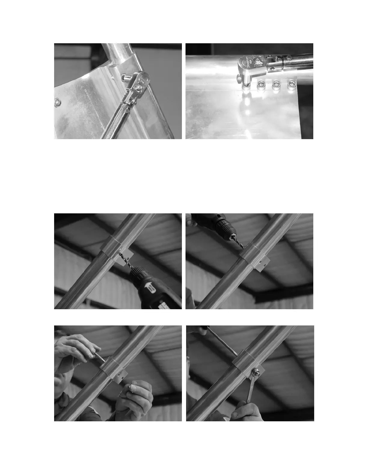
FIG. 26 FIG. 27
Next, locate the pre-drilled ¼” hole that is machined on the side of the upper tube
clamps. Using this ¼” hole as a guide, drill a ¼” hole through the tube on both
sides as shown in Figs. 28 & 29. Insert the ¼” – 20 x 2 ½” socket button head
cap screw through the tube and clamp (Fig. 30). Put the ¼” lock washer on the
bolt, then the ¼” – 20 hex cap nut and tighten as shown in Figs. 31 & 32. Do this
on all four legs.
FIG. 28 FIG. 29
FIG. 30 FIG. 31
11