C11G (Rev.8.2) User Manual
Revision: 01/27/2010 http://cnc4pc.com/TechDocs/C11GR8_2_User_Manual.pdf 4/21
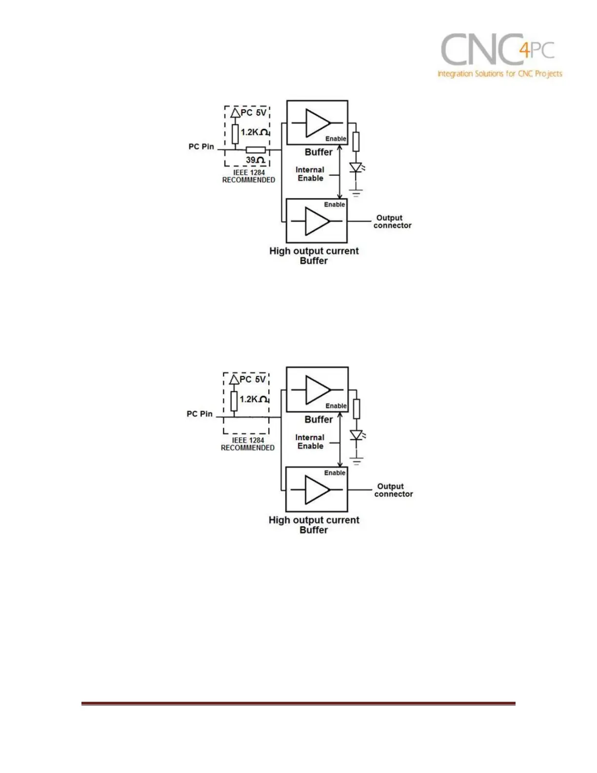
Fig. 1 Simplified functional block diagram for the outputs 2-9.
Parallel Port coupling is done following IEEE 1284 standard recommendation. The
indicator led is driven by a different buffer.
4.2 Outputs 1, 14, 16 and 17 simplified functional block diagram
Fig. 2 Simplified functional block diagram for the outputs 1, 14, 16 and 17.
Note: “Internal Enable” = “External Enable Pin” AND (“SCHP” OR “Bypassed SCHP”)
The “Internal Enable” is the result of an AND Operation between the “External Enable
Pin”and the SCHP operation mode selected by the user.
Note: The output will be deactivated if the board is not connected to the PC
parallel port.
4.3 Input simplified functional block diagram