Do you have a question about the Coaire CIC-12M1Z and is the answer not in the manual?
Instructions to prevent injury to user and property damage.
Warnings related to installation, electrical safety, and product handling.
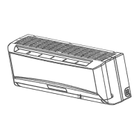
Details on various functions of the indoor unit, including controls and modes.
Details on various functions of the outdoor unit, including components and design.
Physical dimensions of the indoor unit with a size chart.
Physical dimensions of the outdoor unit with a size chart.
Diagram illustrating the refrigerant flow in cooling mode.
Diagram illustrating the refrigerant flow in heat pump mode.
Graph showing operating temperature limits for cooling mode.
Graph showing operating temperature limits for heating mode.
Wiring diagram for the CIC-09M1Z model, showing indoor and outdoor units.
Wiring diagram for the CIH-09M1Z model, showing indoor and outdoor units.
Wiring diagram for the CIC-12M1Z model, showing indoor and outdoor units.
Wiring diagram for the CIH-12M1Z model, showing indoor and outdoor units.
Wiring diagram for the CIC-12M2Z model, showing indoor and outdoor units.
Wiring diagram for the CIH-12M2Z model, showing indoor and outdoor units.
Wiring diagram for the CIC-18M2Z model, showing indoor and outdoor units.
Wiring diagram for the CIH-18M2Z model, showing indoor and outdoor units.
Wiring diagram for the CIC-24M2Z model, showing indoor and outdoor units.
Wiring diagram for the CIH-24M2Z model, showing indoor and outdoor units.
Specifies torque values for installation fittings based on diameter.
Guidance on selecting power cord gauge based on current rating.
Details pipe length, elevation limits, and refrigerant charge for different capacities.
Specifies voltage, frequency, and ambient temperature ranges for electronic control.
Defines symbols and codes for temperature sensors and operational states.
Lists key functions like remote receiving, timer, and compressor protection.
Details various protection mechanisms and error conditions for the unit.
Explains fan speed settings and operation.
Explains fan speed control, anti-freezing, and protection in cooling mode.
Describes the dehumidifying mode operation and its protections.
Describes heating mode operations, including 4-way valve, fan control, and protections.
Details the conditions and actions for the defrosting mode.
Explains automatic selection of cooling, heating, or fan mode based on temperature.
Describes how to activate and operate the forced cooling feature.
Explains the sleep function for energy saving in cooling and heating.
How the unit resumes previous settings after a power failure.
Explains the turbo mode for rapid temperature achievement.
Describes the air purification function and its operation.
Explains the remote sensor function, marked as NOT SUPPORTED.
Description of the indoor unit's display board indicators and their meanings.
Troubleshooting guide for common failure phenomena for different models.
Flowchart for diagnosing issues when the unit does not operate.
Procedure for diagnosing and resolving frequent resetting issues.
Troubleshooting steps for indoor fan speed control issues on 9K/12K models.
Troubleshooting steps for temperature sensor errors.
Diagnostic steps for compressor over-current protection faults.
Identifies EEROM error and points to indoor PCB as the likely cause.
Troubleshooting guide for outdoor unit protection faults.
Steps to diagnose and resolve indoor unit communication errors.
| Brand | Coaire |
|---|---|
| Model | CIC-12M1Z |
| Category | Air Conditioner |
| Language | English |