Do you have a question about the Coaire CIH-18M2Z and is the answer not in the manual?
Instructions to prevent injury to users and property damage during operation.
Warnings related to installation, wiring, and handling to prevent hazards.
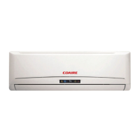
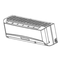
Details operational modes and features of the indoor unit.
Details operational features of the outdoor unit.
Provides physical dimensions for the indoor unit.
Provides physical dimensions for the outdoor unit.
Charts showing operational temperature ranges for cooling mode.
Charts showing operational temperature ranges for heating mode.
Electrical wiring schematics for CIC-09M1Z indoor and outdoor units.
Electrical wiring schematics for CIH-09M1Z indoor and outdoor units.
Electrical wiring schematics for CIC-12M1Z indoor and outdoor units.
Electrical wiring schematics for CIH-12M1Z indoor and outdoor units.
Electrical wiring schematics for CIC-18M2Z indoor and outdoor units.
Electrical wiring schematics for CIH-18M2Z indoor and outdoor units.
Electrical wiring schematics for CIC-24M2Z indoor and outdoor units.
Electrical wiring schematics for CIH-24M2Z indoor and outdoor units.
Specifies torque values for tightening flare nuts during installation.
Guidelines for selecting power cord gauge based on current rating.
Details maximum pipe length and vertical rise for different capacities.
Procedure for removing air from the refrigeration system for proper operation.
Procedure for recovering refrigerant during unit removal or relocation.
Procedure for re-purging air after refrigerant discharge or system breach.
Method for balancing refrigerant charge in the system after installation.
Procedure for removing moisture and non-condensables using a vacuum pump.
Procedure for adding the correct amount of refrigerant to the system.
Specifies voltage, frequency, and ambient conditions for electronic control operation.
Explains symbols used for temperature sensors and operational states.
Lists the various functions and features controlled by the electronic system.
Details the protection mechanisms and error conditions of the unit.
Describes operation when only the fan is active without cooling or heating.
Explains the operation of the unit in cooling mode, including fan control.
Details the operation and protection for dehumidifying mode.
Explains the operation of the unit in heating mode, including fan and valve control.
Conditions and actions for the automatic defrosting cycle in heating mode.
How the unit automatically selects cooling, heating, or fan-only modes.
Procedure for manually forcing the unit into cooling operation.
Energy-saving mode adjusting temperature and fan speed automatically.
Automatically resumes operation after a power interruption.
Function to quickly reach the set temperature.
Operation of the air purification function.
Indicates the 'Follow me' function is not supported.
Explanation of indicators and symbols on the unit's display board.
Tables detailing failure phenomena and corresponding indicator status.
Flowchart for diagnosing unit operation issues based on power and voltage checks.
Procedure to diagnose and resolve frequent automatic resetting issues.
Troubleshooting steps for indoor fan speed issues for specific models.
Troubleshooting for errors related to temperature sensors.
Diagnostic steps for compressor over current protection issues.
Identifies EEROM errors and potential indoor PCB defects.
Troubleshooting for outdoor unit protection faults and power supply issues.
Steps to diagnose and resolve indoor unit communication errors.
| BTU | 18000 |
|---|---|
| Refrigerant | R410A |
| Type | Inverter |
| Noise Level (Outdoor) | 52 dB |
| Cooling Capacity | 18000 BTU/h |