Do you have a question about the Coaire CIC-18M2Z and is the answer not in the manual?
General safety instructions to prevent injury and property damage during operation and installation.
Specific warnings related to the installation process, electrical hazards, and product handling.
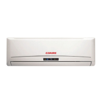
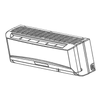
Details on various operating modes and features of the indoor unit, such as fan control and sensors.
Details on features and components of the outdoor unit, including controls and structural elements.
Physical dimensions (W, H, D) of the indoor unit for different capacity models.
Physical dimensions (W, H, D, L1, L2) of the outdoor unit for different capacity models.
Diagram illustrating the refrigerant path during cooling operation.
Diagram showing refrigerant circulation in heat pump mode, including reversing valve.
Chart defining acceptable ambient and indoor temperature ranges for cooling operation.
Chart defining acceptable ambient and indoor temperature ranges for heating operation.
Electrical wiring diagram for the CIC-09M1Z model's indoor and outdoor units.
Electrical wiring diagram for the CIH-09M1Z model's indoor and outdoor units.
Electrical wiring diagram for the CIC-12M1Z model's indoor and outdoor units.
Electrical wiring diagram for the CIH-12M1Z model's indoor and outdoor units.
Electrical wiring diagram for the CIC-12M2Z model's indoor and outdoor units.
Electrical wiring diagram for the CIH-12M2Z model's indoor and outdoor units.
Electrical wiring diagram for the CIC-18M2Z model's indoor and outdoor units.
Electrical wiring diagram for the CIH-18M2Z model's indoor and outdoor units.
Electrical wiring diagram for the CIC-24M2Z model's indoor and outdoor units.
Electrical wiring diagram for the CIH-24M2Z model's indoor and outdoor units.
Recommended torque values for tightening installation connections based on pipe diameter.
Instructions for selecting and connecting power cords based on electrical grade and wire size.
Guidelines for maximum allowable pipe length and vertical elevation difference between units.
Steps for removing air and moisture from the refrigeration piping system.
Procedure for safely evacuating refrigerant when reinstalling the unit.
Steps to re-purge air from the system after re-installation and refrigerant handling.
Procedure for balancing refrigerant levels using the 2-way and 3-way valves.
Steps for creating a vacuum in the refrigeration system using a vacuum pump.
Procedure for charging the system with the correct amount of refrigerant.
Input voltage, frequency, ambient temperature, and amp limits for operation.
Definitions of symbols and codes used in electronic controls and error messages.
Overview of remote receiving, timer, and basic operational functions.
Details on various protection mechanisms like delay, sensor, and current protection.
Explanation of fan-only and cooling mode operations and their controls.
Description of dehumidifying and heating operational modes and controls.
Details on anti-cold wind, auto wind, and evaporator protection in heating.
Conditions and actions for defrosting operation in heating mode.
Explanation of auto mode selection and forced cooling functions.
Explanation of sleep mode and auto restart function.
Details on turbo, ionizer, and follow me functions.
Explanation of the display board's indicators and their meanings during operation.
Table of failure phenomena and corresponding indicator lights for troubleshooting.
Step-by-step diagnostic charts for identifying and resolving specific operational issues.
Troubleshooting steps for frequent resetting during operation.
Diagnosing and resolving indoor fan speed control problems.
Troubleshooting steps for indoor and outdoor temperature sensor malfunctions.
Diagnosing compressor overcurrent protection and EEROM errors.
Troubleshooting outdoor unit protection faults and indoor/outdoor communication errors.
| Brand | Coaire |
|---|---|
| Model | CIC-18M2Z |
| Category | Air Conditioner |
| Language | English |