EasyManua.ls Logo

Coastal Amusements Jacks Hi - User Manual

Default Icon
28 pages
Print Icon
To Next Page IconTo Next Page
Loading...
* 4 Player *
* 4 Player ** 4 Player *
* 4 Player *
USA
USAUSA
USA
(Ticket)
Produced by :
Harry Levy Amusement
Contractor Ltd
Distributed in North and South America exclusively by:
COASTAL AMUSEMENTS, INC.
COASTAL AMUSEMENTS, INC.COASTAL AMUSEMENTS, INC.
COASTAL AMUSEMENTS, INC.
1935 Swarthmore Ave.
Lakewood, NJ 08701 (USA)
Tel: 1-732-905-6662 Fax: 1-732-905-6815
e-mail: sales@coastalamusements.com
visit our web site at: www.coastalamusements.com
Question and Answer IconNeed help?

Do you have a question about the Coastal Amusements Jacks Hi and is the answer not in the manual?

Summary

Commissioning

Receipt Of Machine

Procedure for receiving the machine, unpacking, and initial placement considerations.

Electrical Connection

Guidelines for connecting the machine to the mains power supply via a suitable plug and inlet.

Electrical Supply Entry

Details on the location of the electrical supply connection and the main supply circuit breaker.

Initial Operation

Steps to connect power, start the machine, and initiate the first game play.

Machine Access

Access To Machine Components

Instructions for accessing different parts of the machine, including the playfield, cabinets, and top sign.

Game Operation and Maintenance

The Game

Explanation of the machine's attract mode and active play mode, including coin acceptance.

Priming Playfields With Coins

Recommended procedure for initial coin loading to set up the playfield appearance.

General Care and Maintenance

Guidelines for cleaning and maintaining the machine's surfaces and components for longevity.

Electrical Systems Overview

Circuit Breakers and Fuses

Details on mains supply circuit breakers, motor fuses, and power supply unit circuit breakers.

Logic Board Functionality

Description of the logic board, its components, and switch settings for game configuration.

Sound Board Operation

Information on the sound board, its DIP switch settings, and loudspeaker specifications.

Hopper System

Explanation of the hopper mechanism, coin counting, and processing, including safety warnings.

Power Supplies and Transformers

Details on the power supply units (PSU) and dichroic lighting transformers, including safety warnings.

Feature Interface Board

Description of the feature interface board's role in driving lamps, reels, and bonus channels.

Reel Mechanism

Instructions for accessing and removing the reel mechanism and its components.

Coin-In Sensor and Lockout

Details on the coin entry sensors, their operation, and lockout conditions.

Coin-In Sensor Board

Explanation of the dual beam opto sensors and their connection to the logic board for coin detection.

Counters and Data Port

Information on electro-mechanical counters for tracking game activity and data port access.

Tilt Board Functionality

Description of the tilt board, its inputs, alarm activation, and lighting control.

Alarm Board

Details on the alarm board, its sounder, and its role in tilt and motor jam alerts.

Pusher Box Motor Control

Explanation of the opto-electronic system for monitoring motor load and preventing jams.

Swipe Change Facility

Information on the optional swipe card interface, change board, and its functions.

Machine Lighting

Cabinet Lighting Details

Information on fluorescent lighting in top signs and coin entry areas, and dichroic spot lamps.

Mechanical Systems

Pusher Box Maintenance

Maintenance instructions for pusher boxes, including lubrication and coin scraper system checks.

Troubleshooting and Fault Finding

Fault Finding Methodology

General approach to troubleshooting, including initial checks and wiring inspection.

Systems Checking Procedures

Steps for investigating faults affecting multiple machine sections, focusing on power supply.

Basic Checks for Common Issues

A guide to diagnosing and resolving common symptoms like no start, no sound, or light failures.

Spare Parts List

Commonly Required Spare Parts

A list of frequently needed spare parts with corresponding Harry Levy stock numbers.

Electrical Schematic Diagrams

Electrical System Overview Diagram

A high-level overview of the machine's electrical system components and their interconnections.

Mains Wiring Diagram

Diagram illustrating the mains power input wiring and distribution within the machine.

Tilt Board and Motor Control Wiring

Wiring diagram detailing connections for the tilt board and motor control board.

Logic Board Wiring

Wiring diagram showing the connections to and from the main logic board.

Feature Wiring

Wiring diagram for the feature PCB, including reel unit and playfield lamps.

Tilt, Sound, and Motor Control Wiring

Wiring diagram for tilt signals, sound board, and motor control board connections.

Overview

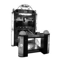
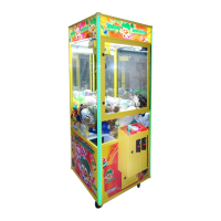
The Jacks Hi is a robust and reliable amusement machine designed for profitable service, featuring a coin-operated game with a pusher box mechanism and reel display. The machine is intended for indoor use and requires a flat, level floor for installation.

Function Description

The core function of the Jacks Hi machine is to provide an interactive coin-operated game experience. Players insert coins into designated chutes, activating a player section for approximately 20 seconds. During this active play mode, the machine's lighting and pusher box mechanism operate, and the reel mechanism may rotate to create visual interest. The objective of the game involves coins falling over an edge, triggering a hopper that counts them. The machine incorporates a logic board with a micro-controller (PIC) and non-volatile RAM, managing game operations, interfacing electronics, and an RS232 data port for data retrieval.

The machine's electrical system includes circuit breakers for protection, a motor fuse for the motor control circuitry, and power supply units (PSUs) with integrated circuit breakers for low voltage circuits. A feature interface board drives the 'card' lamps on the pin perspex and top sign, controls the reel mechanism, and incorporates 'flag-opto' switches for bonus channels, communicating with the main logic board via a serial link.

The reel mechanism, located behind the pin perspex, displays three illuminated graphics. The motor control system uses an opto-electronic method to monitor motor load and stop the motor in case of a jam or restriction. This system detects interruptions in an infrared beam caused by a hole in the rotating motor shaft, generating pulses that are monitored by the motor control PCB. If the pulse rate decreases below a tolerated threshold, the motor supply is cut off via a solid-state relay.

The machine also features electro-mechanical counters in each player section to record coin-in, feature awarded coins out, and coins over the edge/tickets issued. These readings can also be accessed electronically via the RS232 data port. A tilt board, located in the top sign, incorporates a pendulum tilt device and slam tilt switches on the lower compartment doors. Activation of these inputs triggers an audible alarm and switches off the lighting in the top signs, indicating tampering. An alarm board, situated in the No.1 top sign, drives a sounder for tilt and motor jam alarms.

An optional swipe change facility can be integrated, which includes a change board and interface relay. This system provides a pulsed input, an inhibit relay output, and controls the payout hopper.

Usage Features

  • Initial Operation: After connecting the mains supply and switching ON, the Top-Sign and Coin-Entry fluorescent lamps illuminate, and the pusher boxes begin moving. Inserting a coin initiates a tune, increments the coin-in counter, and enables the game for approximately 25 seconds.
  • Attract Mode: When not in active play, the machine's lighting and pusher box mechanism operate continuously, with an attract sound playing at intervals and the reel mechanism rotating to create interest.
  • Active Play Mode: Correctly inserted coins activate a player section for about 20 seconds, allowing the player to benefit from the coin's effects. Incorrect coins fall into reject trays.
  • Playfield Priming: Each player section requires approximately 900 coins, with the first 850 manually placed and the final 50 played through the coin entry slots for optimal visual appearance.
  • Tilt/Slam Tilt Alarm: The anti-abuse 'slam-tilt' alarm can be tested by thumping a lower cabinet door, causing the alarm to sound and the top sign lights to go out. All count hoppers run, directing fallen coins to the cashbox. A tilt pendulum sensor detects machine movement from level. Alarms stop games for about 10 seconds.
  • Pusher Drive Motor Safety: A safety feature stops the pusher drive motor if a jam or restriction occurs. Resetting this feature requires operating a discreetly located reset switch in the roof section.
  • Access: The playfield glass can be hinged backward and removed. Coin-entry doors, lower cabinet access doors, and cashbox access doors are secured with locks. The top-sign artwork panels can be unscrewed for access, though dangerous voltages are present, requiring trained personnel.
  • Logic Board Settings: DIP switches on the logic board allow for configuration of "Tickets On Coin-In" and "Win Table Select" settings, influencing game payout. SW2 poles 1-3 set the nominal percentage payout, and pole 4 is used to reset payout percentage registers, generating a 'coin-in' sound upon reset confirmation.
  • Sound Board Settings: DIP switches on the sound board control attract music intervals and the number of messages played in attract mode.
  • Bonus Empty Caption: If tickets run out, the 'Bonus empty when light' caption on the coin entry door illuminates continuously.
  • Beacon Light: Red beacon lights on top of each top sign flash for bonus wins and remain permanently on to alert staff of problems.

Maintenance Features

  • General Care & Maintenance: The machine is designed for years of profitable service with regular cleaning.
    • Plastic and Glass Fibre surfaces should be cleaned with a water-based detergent and finished with furniture polish.
    • Laminated Cabinet trims should be cleaned with a non-aggressive cleaner and finished with furniture polish.
    • Glass and Chrome surfaces should be cleaned with a quality window cleaning solution.
    • Important: Avoid caustic or abrasive cleaners and always follow manufacturer instructions for cleaning products.
  • Bearings and Mechanical Components: The Jacks Hi uses 'sealed for life' bearings and high-quality mechanical components that do not require regular greasing or servicing.
  • Initial Inspection: An initial inspection is recommended after approximately two months of usage to check for wear on moving parts and adjust as needed. Subsequent inspections should be annual.
  • Pusher Boxes: Pusher boxes are mounted on Accuride slide bearings. An annual check to remove dust and apply a light coat of grease is recommended. The coin scraper system should be checked for integrity and smooth operation, with suspect parts replaced.
  • Fault Finding - Electrical Systems:
    • Safety First: If an electrical fault occurs, SWITCH THE MACHINE OFF.
    • Basic Checks: Verify mains supply, circuit breaker settings, correct mating of plugs and sockets, and ensure no wires are trapped, damaged, or broken, and all are properly secured.
    • Wiring Check: Perform a visual inspection of wiring. For apparently intact wires, a continuity tester may be needed.
    • Device Testing: Disconnect the machine from the mains supply. Check the physical condition and operation of the suspect device (remove if necessary). Bench test with a suitable power supply if possible.
    • PCB Faults: PCBs are generally not user serviceable; return faulty boards to the distributor for repair.
    • System Checking: For faults affecting two back-to-back sections, investigate the power supply system first. Check plugs, wiring, and circuit breakers. Refer to schematics for power connections and voltages. If a fault is not visual, disconnect PSU outputs, check PSU function, then reconnect loads one at a time to isolate the faulty system.
  • Motor Fuse Replacement: The motor fuse, located on the motor control PCB, must only be replaced with an identical item.
  • Circuit Breaker Reset: To reset a tripped mains supply circuit breaker, depress the yellow center back into the device body. For PSU circuit breakers, press the protruding white button back into the device body.
  • Reel Mechanism Maintenance: The reel band is removable by lifting plastic tabs and pressing inward on the roller assembly. Illumination lamps can be replaced by turning the lamp holder a quarter turn anti-clockwise. Refitting the reel band requires ensuring correct orientation for the optical position sensor.
  • Opto-Sensor Check (Motor Control PCB): An LED on the Motor Control PCB indicates the opto-sensor output. In normal operation, it appears continuously ON due to high pulse repetition. Manually rotating the motor shaft and observing the LED turning on and off as the hole passes between sensors can verify sensor operation.
  • Dichroic Lamp Replacement: Low voltage dichroic spot lamps can be replaced by pulling the old bulb free and pushing a new one in. Allow lamps to cool before handling.

Coastal Amusements Jacks Hi Specifications

General IconGeneral
ManufacturerCoastal Amusements
CategoryArcade Game Machines
Players1
MonitorLCD
Bill AcceptorOptional
TypeCrane
Power Requirements110V
DisplayYes

Related product manuals