4 • Important: Always read and follow the information box instructions.
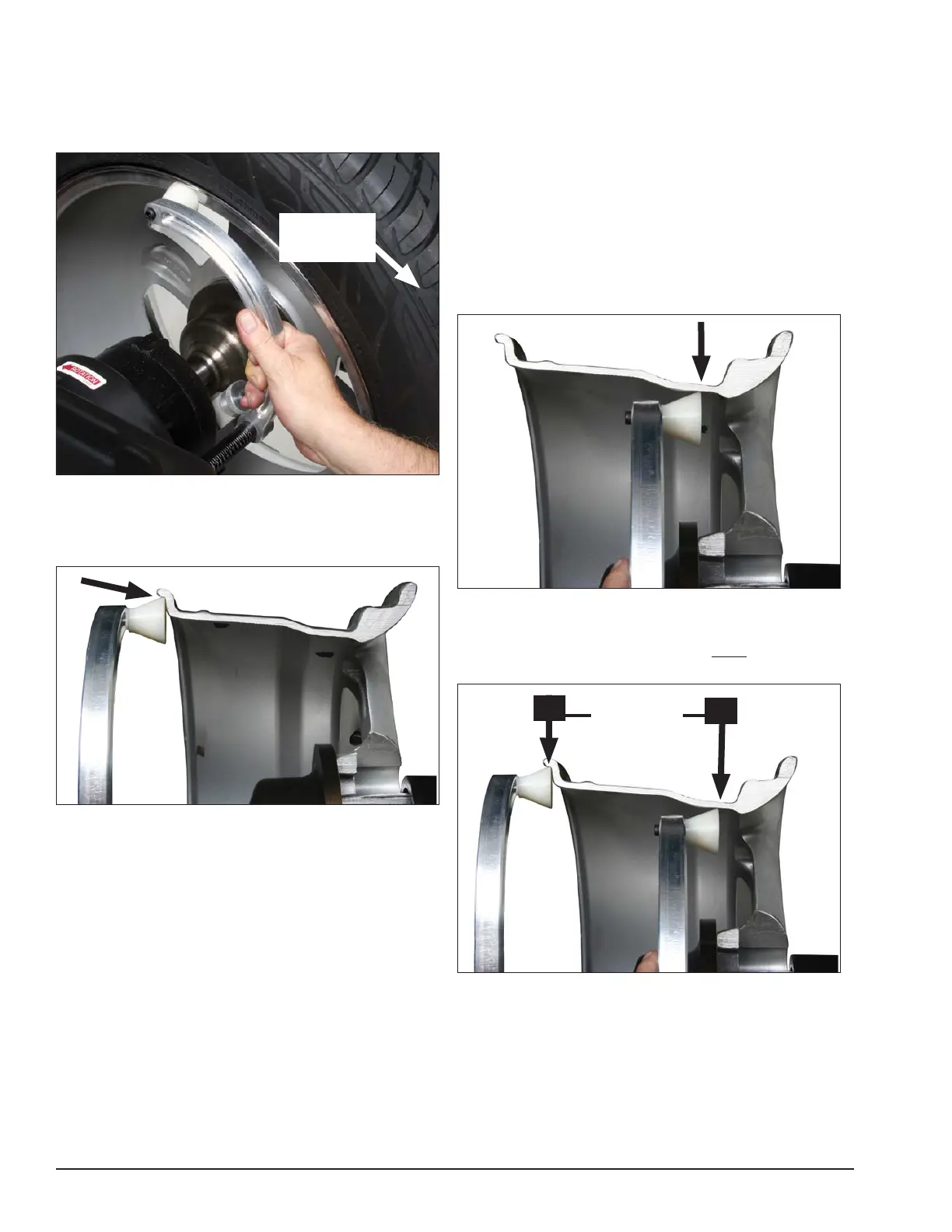
When prompted by balance r instructions, use the
offset arm (figure 6A) to enter A & D measurements
automatically. Pull the arm out and up against the wheel
flange; hold it still at the clip-on weight location (figure
6B), against the wheel flange, and wait for the BEEP.
Figure 6A - Automatic A&D Measurement At Clip-on Weight
Location
Be sure to place the offset arm on the wheel flange at
the clip- on weight location as shown figure 6B.
Figure 6B - Clip-on Weight Location Viewed on a Cut-Away
Rim for Clarification.
Note: Use the offset arm to automatically measure
the A & D dimension for all balancing modes except
Patch Static (refer to page 13 Patch Weight Balance).
Note: Refer to page 7 to measure the A dimension
manually using the offset arm.
Note: The T2 - Tape Direct Select™ Weight position
is the only mode that requires the A2 & D2 dimension
measurements.
Note: Use laser locators for correct positioning of
the T2 - Tape Direct Select™ Weight position, refer to
pages 5 - 6.
If the T2 - Tape (hidden Tape-A-Weight®) location is
selected, use the offset arm to enter A2 & D2 measure-
ments automatically. After the A & D measurement is
entered, move the arm from the clip-on weight location
to the inner area of the wheel; up against the rim at the
outboard weight placement location (see figures 7A &
7B). Wait for the BEEP.
Figure 7A - Hidden Weight Location Viewed on a Cut-Away
Rim for Clarification.
Important: The A2 measurement must be at least 2
inches greater than the A1 measurement.
Figure 7B - T2-Tape (Hidden Tape-A-Weight®) Keep At Least
2-inches Between A1 and A2 Measurement
Offset Arm
In Home
Position
At least
2-Inch
minimum
difference
A1
A2