Installation guide
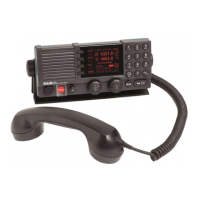
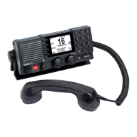
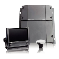
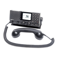
SAILOR 6300 MF/HF Transceiver Unit
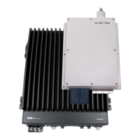
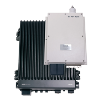
& Antenna Tuning Unit 150/250/500W
How to install the Transmitter Antenna
How to install the Antenna Tuning Unit mounting bracket
How to install the Transceiver Unit 150/250W
1. Nut M10
2. Tooth lock washer M10
3. Fitting for mast
4. Mountingplate for ATU
5. Treadrod M10
Disclaimer
105 mm 350 mm
360 mm
391 mm
35 mm
150 mmMin.
379 mm
150 mmMin.
360 mm
Space for
cable access
Space for
service
4 x ø8mm
443 mm
4 x ø6mm
23.5 mm
88 mm
145 mm
500Min. mm
Space for airflow
and service
3
4
3 5
4
2
1. Pan head screw M6x16 mm
2. Washer M6
3. Hexagon head screw M6x10 mm
4. Flat washer ø6.4xø12x1.6 mm
How to install the Antenna Tuning Unit 150/250W
Space for cable and
service access
164 mm 164 mm
271 mm
150Min. mm
75 mm
12 mm
80 mm
200 mm
352 mm
504 mm
500Min. mm
50Min. mm
Space for
service access
Space to nearest overhang
80 mm
290 mm
1000 mm
200 mm
4
2
1
1
3
3
5
6
Wire length 4 metres
Optional accessories:
Mounting plate and ttings for mast part no 737589.
Mounting plate only - part no 737588.
Cable fitting
In general a 12 metres antenna installation is preferred and can be made using an 8
metres whip and 4.5 metres feeder or a 10 metres whip and 2.5 metres feeder. In both
cases the whip should be mounted on a pole providing sufcient height to have the
Antenna Tuning Unit mounted such that it allows for the feeder to be erected at an
angle of 45 to 60 degrees, creating a combined 12 metres vertical antenna system.
The feeder wire is terminated at the antenna horn at the top of the Antenna Tuning
Unit. Use a supporting insulator near the ATU to carry mechanical stress from the
feeder wire. Use a short exible part of the feeder wire between the supporting
insulator and the ATU horn in order not to ap-
ply mechanical stress to the antenna horn.
To maximize the radiated power and avoid ash
over, keep distance to metal parts as long as
possible, preferable more than 100 mm. Use a
short direct ground connection from the ground
clamp at the bottom end at the Antenna Tuning
Unit to nearest suitable metal ground plane.
It is recommended to use the ATU mounting
bracket for the physical tting of the ATU.
For further information, download the installation
manual 98-144591 at www.cobham/satcom.
Optional accessories:
Antenna connection kit
part no 406300-960.
1. Shackle
2. Isolator
3. Wire clamp
4. Wire
5. Cable tie
6. Wire lug
Weight: 19 kg (41.9 lbs) Weight: 3.3 kg (7.3 lbs)
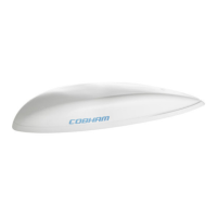
A passive type antenna of 6-10m electrical length is recommended as receiver an-
tenna. The antenna should be erected well in the clear and kept away as far as possible
from electrical equipment to minimize noise interference.
It is recommended to provide the installation with an impedance matching transfor-
mer inserted at the antenna. The matching transformer grounding cable should be as
short as possible and connected to ground through welded bolt. The antenna feed-in
shall be by coaxial cable.
In case a passive antenna for practical reasons cannot be installed, it may be repla-
ced by an active type antenna. It is however, important to emphasize that an active
antenna may decrease the receiving capabilities through reduction in received signal
level and receiver dynamic range. The installation of an active antenna should follow
the same installation precautions as for a passive type antenna.
How to install the Receiver Antenna
Any responsibility or liability for loss or damage in connection with the use of this product and the accompanying documentation is disclaimed
by Thrane & Thrane A/S. The information in this manual is provided for information purposes only, is subject to change without notice and may
contain errors or inaccuracies. Manuals issued by Thrane & Thrane A/S are periodically revised and updated. Anyone relying on this information
should acquire the most current version e.g. from www.cobham.com/communications-and-connectivity/satcom, Service and support, or from
the distributor. Thrane & Thrane A/S is not responsible for the content or accuracy of any translations or reproductions, in whole or in part, of this
manual from any other source. In the event of any discrepancies, the English version shall be the governing text.
Thrane & Thrane A/S is trading as Cobham SATCOM.