Page 3 of 8
Notes:
1. Larger wires and tight connections will provide longer service life for components. For high current wires it is highly recommended
that terminal blocks or soldered connections be used with shrink tubing to protect the connections. Do not use insulation displacement
connectors (e.g., 3M Scotchlock type connectors).
2. Route wiring using grommets and sealant when passing through compartment walls. Minimize the number of splices to reduce voltage
drop. All wiring should conform to the minimum wire size and other recommendations of the manufacturer and be protected from moving
parts and hot surfaces. Looms, grommets, cable ties, and similar installation hardware should be used to anchor and protect all wiring.
3. Fuses or circuit breakers should be located as close to the power takeo points as possible and properly sized to protect the wiring and
devices.
4. Particular attention should be paid to the location and method of making electrical connections and splices to protect these points from
corrosion and loss of conductivity.
5. Ground termination should only be made to substantial chassis components, preferably directly to the vehicle battery.
6. Circuit breakers are very sensitive to high temperatures and will “false trip” when mounted in hot environments or operated close to their
capacity.
Connect the light head’s black and red wires to the vehicle system’s ground and positive (+12 or +24 VDC), respectively. Note: For
Perimeter Lights the white ash pattern selection wire must be protected from contact with the system ground to prevent
inadvertent changes to the ash pattern. This can be accomplished by sealing or capping the end of the wire.
Wiring Instructions:
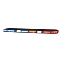
LED Perimeter Light Models
Wire Function
Red White Black
Models 45, 65, 85 - Perimeter Congurations +12 or +24 Program
Ground45STR & 65STR - LED STT, Red Stop or Turn Tail
45STA & 65STA, Amber Turn none
Power Requirements:
LED Perimeter Lights are designed to be long life, full signal, light weight and low current draw.
The following table lists the number of LED’s in each model and the average current draw for various conditions.
Part Number #of LEDs
Average Current Draw, Amps
Steady
Burn
13.8VDC
Flashing
13.8VDC
Steady
Burn
24.0VDC
Flashing
24.0VDC
45, 45STA, 45STR - 7X3 PERIMETER 62 1.0 0.5 0.5 0.3
65 - 6X4 PERIMETER 76 1.0 0.5 0.5 0.3
85 - 9X7 PERIMETER 124 1.5 0.8 0.8 0.4
65STR - 6X4 - RED(STOP OR TURN CONFIG.) 54 0.7 0.4 0.4 0.2
65STR - 6X4 - RED (TAIL CONFIG.) 54 0.05 N/A 0.04 N/A
65STA - 6X4 - AMBER TURN 54 0.7 0.4 0.4 0.2