EasyManua.ls Logo

Code 3 H2 Covert User Manual

Code 3 H2 Covert
12 pages
To Next Page IconTo Next Page
Page #1 background imageLoading...
Page #1 background image
Page 1 of 12
H
2
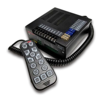
Covert™ Remote Siren System with
Hand-Held Controller
Introduction:
The H
2
Covert
TM
uses an easily concealable remote hand-held con-
troller coupled to an electronic siren, all designed to meet the needs
of emergency vehicles. This series incorporates many of the popular
features of existing Code 3
®
siren systems as well as some new
features such as new siren tones, 4 auxiliary controls, EU Lock, and
Title 13 Compliance. The purpose of this document is to aid in the
setup and installation of the H
2
Covert, and to provide instructions for
its proper operation.
Contents:
Introduction.......................................01
Standard Features.......................................02
Unpacking & Pre-Installation..................................02
Installation & Mounting.......................................02
Connection..................................03-04
Operation.......................................05-09
Specications.......................................10
Maintenance.......................................10
Parts List.......................................10
Troubleshooting.......................................11
Warranty.......................................12
IMPORTANT! Read all instructions before installing and using. Installer: This manual must be delivered to the end user.
WARNING!
Sirens are an integral part of an effective audio/visual emergency warning system. However, sirens are only short range second-
ary warning devices. The use of a siren does not insure that all drivers can or will observe or react to an emergency warning signal,
particularly at long distances or when either vehicle is traveling at a high rate of speed. Sirens should only be used in a combination
with effective warning lights and never relied upon as a sole warning signal. Never take the right of way for granted. It is your responsibility to
be sure you can proceed safely before entering an intersection driving against trafc, or responding at a high rate of speed.
The effectiveness of this warning device is highly dependent upon correct mounting and wiring. Read and follow the manufacturers instruc-
tions before installing this device. The vehicle operator should check the equipment daily to insure that all features of the device operate cor-
rectly.
To be effective, sirens must produce high sound levels that potentially can inict hearing damage. Installers should be warned to wear hearing
protection, clear bystanders from the area and not to operate the siren indoors during testing. Vehicle operators and occupants should assess
their exposure to siren noise and determine what steps, such as consultation with professionals or use of hearing protection should be imple-
mented to protect their hearing.
This equipment is intended for use by authorized personnel only. It is the user’s responsibility to understand and obey all laws regarding emer-
gency warning devices. The user should check all applicable city, state and federal laws and regulations. Code 3, Inc., assumes no liability for
any loss resulting from the use of this warning device.
Proper installation is vital to the performance of the siren and the safe operation of the emergency vehicle. It is important to recognize that
the operator of the emergency vehicle is under psychological and physiological stress caused by the emergency situation. The siren system
should be installed in such a manner as to: A) Not reduce the acoustical performance of the system, B) Limit as much as practical the noise
level in the passenger compartment of the vehicle, C) Place the controls within convenient reach of the operator so that he can operate the
system without losing eye contact with the roadway.
Emergency warning devices often require high electrical voltages and/or currents. Properly protect and use caution around live electrical con-
nections. Grounding or shorting of electrical connections can cause high current arcing, which can cause personal injury and/or severe vehicle
damage, including re.
PROPER INSTALLATION COMBINED WITH OPERATOR TRAINING IN THE PROPER USE OF EMERGENCY WARNING DEVICES IS ESSENTIAL TO
INSURE THE SAFETY OF EMERGENCY PERSONNEL AND THE PUBLIC.
Installation and Operation Instructions
WARNING!
• Sirens produce loud sounds that may damage hearing
• Wear hearing protection when testing
• Use siren only for emergency response
• Roll up windows when siren is operating
Avoid exposure to the siren sound outside of the vehicle

Questions and Answers:

Code 3 H2 Covert Specifications

General IconGeneral
BrandCode 3
ModelH2 Covert
CategorySecurity System
LanguageEnglish

Summary

Introduction to the H₂Covert System

H₂Covert System Overview

Overview of the H₂Covert™ remote siren system with hand-held controller for emergency vehicles.

Manual Purpose and Scope

Document purpose is to aid in setup, installation, and operation of the H₂Covert system.

Page 1 Safety and Warning Information

Hearing Protection and Siren Use Safety

Warnings about siren loudness, potential hearing damage, and proper usage during emergencies.

Installation and Operation Precautions

Emphasizes correct mounting, wiring, daily checks, and operator assessment of noise exposure.

Electrical Safety and Fire Hazards

Caution regarding high electrical voltages, currents, grounding, and potential fire hazards.

H₂Covert Standard Features and Unpacking

H₂Covert System Feature List

Details audio, control, operational, and compliance features of the H₂Covert system.

Unpacking and Pre-Installation Checks

Instructions to inspect the unit and parts for transit damage and identify included components.

Installation and Mounting Guidelines

Controller and Amplifier Mounting

Guidance on mounting controller for visibility and amplifier in a protected, ventilated area.

Controller to Amplifier Connection

Details the RJ45 connector used for connecting the hand-held controller to the amplifier.

Page 2 Installation Safety and Precautions

Secure Mounting and Operator Visibility

Ensures devices are securely fastened and mounted for operator visibility and convenient access.

Amplifier Environmental Protection Needs

Highlights the amplifier's non-waterproof nature and the need for protection from elements.

Page 3 Wiring and Connection Safety Guidelines

Wire Gauge and Connection Best Practices

Recommendations for wire size, terminal blocks, and connection protection for high current applications.

Fuse and Circuit Breaker Sizing

Guidance on proper sizing and placement of fuses/breakers to protect wiring and devices.

Glass Fuse Limitations

Warns against using certain glass fuses for continuous duty due to temperature sensitivity.

Electrical Connections Procedure

Battery Disconnection and Power Wiring

Instructions for disconnecting the battery and connecting power wires with correct polarity.

Wire Gauge Requirements for Connections

Specifies user-supplied wire gauges for various connections like speaker, input, and ground.

Controller and Amplifier Connection

Connecting the hand-held controller to the amplifier using the RJ45 connector and extension cord.

Dip Switch Configuration for System Features

Instructions to configure dip switches on the siren amplifier for system features.

Power Wire Connection Details

Details on connecting +12V and NEG wires to the pluggable connector for power.

Advanced Electrical Connections

Speaker Connection Requirements

Guidance on connecting speakers, including impedance and parallel wiring for dual speakers.

Horn Ring Transfer Wiring

Instructions for wiring the horn ring transfer circuit for siren tone control via the vehicle horn.

Chassis Ground Connection Importance

Emphasizes the importance of connecting the siren enclosure to a good vehicle chassis ground.

Door/Park-Siren-Off Input Wiring

Details wiring the input to automatically deactivate siren tones when the vehicle is shifted into PARK.

Radio Rebroadcast Connection

How to connect the line output signal for radio rebroadcast and adjust radio gain.

Connector and Wire Termination Best Practices

Instructions for plugging in connectors and securing wires, ensuring no shorts or sharp edges.

Lightbar Power Wiring

Connecting lightbar power wires to the 7-position screw terminal block with current limits.

+12VLTG Terminal Connections

Connecting +12VLTG terminals to a 12V source using appropriate gauge wire for lighting outputs.

Short Circuit Verification Steps

Steps to verify no short circuits exist between positive leads and the vehicle chassis before final connection.

System Operation Guide

Electromagnetic Interference Warning

Caution regarding potential interference between electronic devices and testing procedures.

Push to Talk and Radio Gain Adjustment

Instructions for adjusting gain trimmers on the amplifier to reduce distortion for PA and radio.

Horn Ring Feature Operation

How the horn ring can be used to control siren sounds, including tone selection and scrolling.

Horn Ring Output Examples

Table showing siren status and output based on light status and horn ring actions (tapping/holding).

Footswitch/Pursuit Feature Option

Notes that a footswitch can substitute the Horn Ring feature for siren control.

Park Kill Feature Operation

How the Park Kill feature deactivates siren tones when the vehicle is shifted into park or a door is opened.

California Siren Tone Warnings

Important warnings about specific siren tones (Wail, Yelp) being the only recognized for right-of-way.

EU Lock Feature Configuration

Explains how to enable and set minimum light levels for the EU Lock feature using dip switches.

Advanced System Operation Features

Auto Siren Feature Activation

Enables automatic siren activation with Lighting Level 3 and automatic shut-off when Level 3 is turned off.

Programmable Siren Tone Selection

Instructions on how to change the factory presets for SIR1 and SIR2 siren tones.

Programmable Air Horn Pitch Tones

Procedure to change the two available tones for the Air Horn feature.

Auxiliary Light Control Button Functions

Describes the function of the four auxiliary buttons and their special modes (Momentary, Gun Lock).

Keypad Backlight Dimming and Shut Off

How to adjust keypad backlight levels (Brightest, Bright, Dim, Off) using the STBY button.

California Title 13 Compliance Settings

Enables Title 13 compliance mode, disabling certain tones and restricting Air Horn with lights.

Configurable Dip Switch Functions

Dip Switch #1: California Title 13 Mode

Enables Title 13 compliance, disabling specific tones and restricting Air Horn with light levels.

Dip Switch #2: Auto Siren Feature

Enables automatic siren activation with Lighting Level 3.

Dip Switch #3: AUX3 Momentary Mode

Configures AUX3 to be active only while the button is pressed.

Dip Switch #4: Park Kill Light Level 3 Feature

Links Park Kill to reduce light level from 3 to 2 when the siren is disabled.

Dip Switch #5: AUX4 Gun Lock Mode

Configures AUX4 to activate for 10 seconds after pressing the button.

Dip Switch #6: Horn Ring Scrolling Disable

Disables horn ring scrolling, forcing it to emulate Manual or Air Horn buttons.

Dip Switch #7: Horn Ring Emulation

Sets horn ring to emulate either the 'MANUAL' or 'AIR HORN' button.

Dip Switches #8 & #9: EU Lock Feature

Enables EU Lock feature, ensuring minimum light level is active with siren tones.

Dip Switch #10: Reserved Setting

This dip switch is reserved and should be left in the 'OFF' position.

Handheld Controller Operation Guide

Microphone and Talk Function

The microphone is used for talking through the siren speaker.

Light Level (LEV1-LEV3) Button Operations

Details how LEV buttons control light loads and interact with EU Lock and Auto Siren features.

Auxiliary (AUX1-AUX4) Button Functions

Explains how AUX buttons supply power to connected loads, with modes determined by dip switches.

RAD (Radio Rebroadcast) Button

Over-rides siren tones with PA audio; returns to siren tone upon release.

MAN (Manual Tone) Button

Activates the Manual siren tone, overriding other tones and potentially activating minimum light level.

AIR (Air Horn) Button

Activates the Air Horn tone, allowing pitch adjustment with the STBY button.

SIR (Siren Scroll) Button

Cycles through available siren tones (Wail, Yelp, Hi-Lo, etc.) and can activate minimum light level.

SIR1/SIR2 (Siren Tone 1/2) Buttons

Activates preset siren tones (SIR1=Wail, SIR2=Yelp) and can activate minimum light level.

STBY (Standby) Button Functionality

Shuts off active siren tones and is used for keypad dimming mode and tone preset changes.

PTT (Push To Talk) Button

Activates the PA function, routing audio through the siren speaker.

Power/Volume Control Operation

Controls unit power (on/off) and maximum volume by rotating a wheel.

Technical Specifications

Siren and Electrical Specifications

Details input voltage, current, output voltage, and operating temperature range.

Physical Dimensions and Weight

Provides dimensions and approximate weight for the controller and the main siren unit.

Mounting and Compliance Standards

Describes mounting methods and compliance with SAE J1849 and California Title 13.

Lighting Section Current Limits

Lists maximum current limits for each warning light control level (Level 1-3, AUX 1-4).

Maintenance and Service Information

Troubleshooting Guidance Overview

Advises consulting the troubleshooting guide and checking wires for common difficulties.

Factory Service and Warranty Policy

Information on warranty service, repair options, and voiding the warranty by unauthorized service.

System Parts List

Lists part numbers, descriptions, and quantities for system components.

Troubleshooting Guide for Common Problems

No Siren Output or Fuse Issues

Addresses no siren output, blown fuses, and reversed polarity issues with remedies.

Speaker and Volume Problems

Troubleshooting low/garbled tones, high speaker failure rate, and incorrect speaker wattage.

Tone Ramp and PA/RRB Issues

Resolves issues like tones continuing after manual release, low PA/RRB volume, and siren self-activation.

PA Operation Without Siren Output

Diagnoses PA operation but no siren output, often related to Park Kill or RRB switch settings.

Manufacturer Limited Warranty Policy

Warranty Coverage Period

States the limited warranty extends for sixty (60) months from the date of purchase.

Warranty Voidance Conditions

Lists conditions that void the warranty, including tampering, misuse, and unauthorized modifications.

Exclusion of Other Warranties

Disclaims express or implied warranties for merchantability, quality, or fitness for a particular purpose.

Limitation of Liability Clause

Defines the manufacturer's liability limits for product claims, excluding consequential damages.

Product Returns and Service Procedure

Return Goods Authorization Process

Instructions to contact the factory for an RGA number before shipping a product for repair or replacement.

Related product manuals