Code Blue
•
259 Hedcor Street
•
Holland, MI 49423 USA
•
800.205.7186
•
www.codeblue.com
GU-145-Epage 6 of 23
IA3100
Administrator Guide
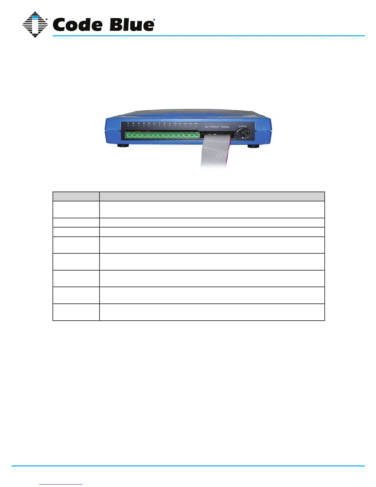
Connect Wiring Harness
The green, 14-pin Phoenix connector will plug into the IA3100. This connector is where all wiring
connections are made.
Pin# Function
1
2
Power input (12-30 volts DC or 12-24 volts AC)
3 Tip (Telephone Line)
4 Ring (Telephone Line)
5
6
Auxiliary Output #1 (100mA)
7
8
Auxiliary Output #2 (100mA)
9
10
Auxiliary Input #1
11
12
Auxiliary Input #2
13
14
Auxiliary Input #3
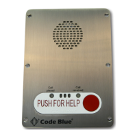
Install the IA3100 Faceplate into Unit
1. The phone/faceplate assembly is installed in the unit using six counter-sunk security
screws.
Installation (continued)
Connect Wiring Harness
The green, 14-pin Phoenix connector will plug into the IA3100 (this connector is where
all wiring connections are made).
Power input (12-30 volts DC or 12-24 volts AC)
Auxiliary Output #1 (100mA)
Auxiliary Output #2 (100mA)
Install the IA3100 Faceplate into Unit
1. The phone/faceplate assembly is installed in the unit using six (6) counter-sunk
security screws.